


背景:
在自己搭建的二维绘图设计软件中,需要导入CAD文件,并进行二次分析操作测试. 所以,CAD图元的解析就是个问题.这里记录一下Mesh图元的解析过程, 比较简单,仅作记录
过程:
Mesh 主要包括 顶点 和面片的数量
其二者之间保存了面的数量,而面包含了顶点的绘制顺序..
按照里面的顺序,我们进行一番分析:
1.总共5个顶点
1->(410,-90,0)
2->(490,-80,0)
3->(470,-50,0)
4->(490,-10,0)
5->(420,-30,0)
2.面的顺序是
1->(1,2,3)
2->(-1,4,5)
按照三维绘制的顺序: 顺反逆正(三维世界中绘制的次序)
所以,实际上的点的坐标,要做取反
1->(-410,90,0)
2->(-490,80,0)
3->(-470,50,0)
4->(-490,10,0)
5->(-420,30,0)
//规则,如果遇到下一个顶点的 次序为负数.那么就会使用第一个面的首个顶点做为自己的起始绘制点
->上述的绘制的点的顺序是为
第一个面->(1,2,3)
第二个面->(1,4,5)
意味着,其共用顶点.
关键代码:
 public static void DxfConvertXplote(netDxf.Entities.PolyfaceMesh dxfmesh, XPlotePolyline polyLine)
        {
            polyLine.isLineClose =true;
            int count = dxfmesh.Faces.Count;
            PointCollection points = polyLine._pointCollection;
            points.Clear();
            //输出信息.
            //输出顶点信息
            int RecorStartIndex = -1;
            for (int i = 0; i < count; i++)
            {
                PolyfaceMeshFace temp = dxfmesh.Faces[i];
                if (temp.VertexIndexes.Count < 3) continue;
                int index1 = temp.VertexIndexes[0];
                if (index1 > -1)
                {
                    RecorStartIndex = index1;
                }
                int index2 = temp.VertexIndexes[1];
                int index3 = temp.VertexIndexes[2];

                PolyfaceMeshVertex p1 = dxfmesh.Vertexes[RecorStartIndex - 1];
                PolyfaceMeshVertex p2 = dxfmesh.Vertexes[index2-1];
                PolyfaceMeshVertex p3 = dxfmesh.Vertexes[index3-1];

                //添加一个面.
                points.Add(new System.Windows.Point(-p1.Position.X, -p1.Position.Y));
                points.Add(new System.Windows.Point(-p2.Position.X, -p2.Position.Y));
                points.Add(new System.Windows.Point(-p3.Position.X, -p3.Position.Y));
            }
        }
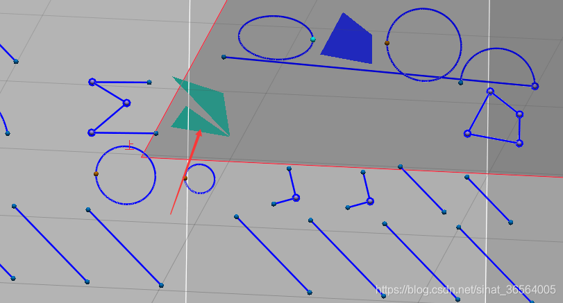
看最后结果:
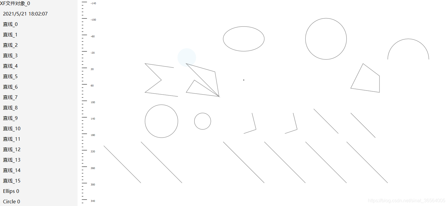


 1064
1064

 被折叠的 条评论
为什么被折叠?
被折叠的 条评论
为什么被折叠?
 到【灌水乐园】发言


