


文章目录
- 对于由输入端口驱动的单元来说,输入slew /transition是未知的。
- 同样,对于驱动输出端口的单元来说,负载也是未知的。
- Thus, designers need to provide the input transition time for the input signals and the external load that the output port will see.
- 如果没有指定,则过渡时间假定为0,即有一个明显的斜坡(相当于驱动能力无穷大),
- 负载假定为0,即没有外部负载。两种情况都是非常乐观的情况。
10.1 Drive Strength
The SDC command to specify the equivalent resistance of the driver is:
set_drive [ -rise ] [ -fall ]
 [ -min ] [ -max ]
 resistance_value port_list
-
注意,它所提供的值实际上是电阻值——它是驱动能力的倒数。 电阻越高, 驱动能力越低(过渡时间越长),反之亦然。
-
-rise或者-fall用于指定驱动(实际上是驱动器的电阻)信号上升还是下降。当不使用-rise和-fall时,指定值适用于上升输入和下降输入。
-
-min或者-max用于指定电阻是最小电阻还是最大电阻。 **最小电阻意味着更高的驱动能力,具有更快的过渡速度,因此最小电阻用于保持分析。**类似地,最大电阻用于建立分析。如果没有使用-min或者-max限定符,那么指定的值用于建立分析也用于保持分析。
-
通常,使用set_drive指定输入slew是一种不太常用的方法。
10.2 Driving Cell
10.2.1 set_driving_cell
set_driving_cell [ -lib_cell lib_cell_name]
 [ -rise ] [ -fall ]
 [ -min ] [ -max ]
 [ -library lib_name]
 [ -pin pin_name]
 [ -from_pin from_pin_name]
 [ -multiply_by factor]
 [ -dont_scale ]
 [ -no_design_rule ]
 [ -clock clock_name]
 [ -clock_fall ]
 [ -input_transition_rise rise_time]
 [ -input_transition_fall fall_time]
 port_list
10.2.1.1 Driver Cell Name
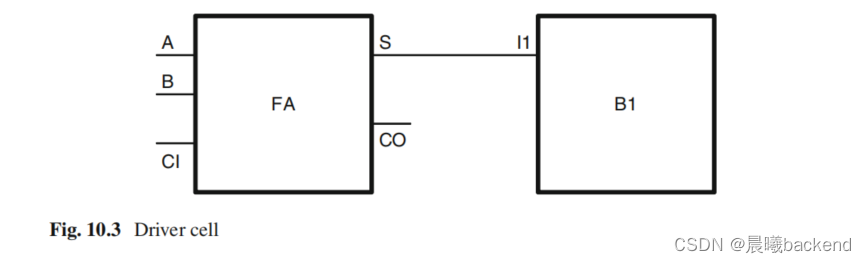
- The -lib_cell switch is used to specify the cell which acts as the driver for the pin. In Fig. 10.3 , the input I1 of the block B1 is being driven by the cell FA . Thus, this cell should be specified as the -lib_cell
10.2.1.2 Min/Max, Rise/Fall
- 当设计者需要为输入引脚的 rise transition指定一个驱动单元,为输人引脚的fall transition指定另一个驱动单元的时候,应使用-rise/-fall限定符。如果没有使用限定符,那么上升和下降过渡使用相同的驱动单元。
- The -min/-max qualifier is used, when a designer wants to specify different driving cells for setup (max) analysis and another driving cell for hold (min) analysis.
10.2.1.3 Library
- 有时,工具中会加载多个库,这时会出现多个库中有相同名称的单元。
- 指定开关-library,只是为了更明确,保证指定的是希望的单元。
10.2.1.4 Pin
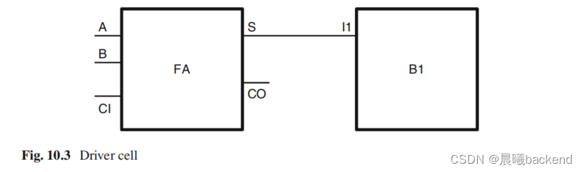
- 以图10.3所示的驱动单元为例,驱动单元有多个输出。这时,设计者应该指定-pin开关用来说明哪一个输出用于驱动输入。
- 虽然已知单元FA是驱动器(对于电路单元B1的11),但是FA的输出引脚S和CO的驱动能力可能不同,所以设计者应该说明哪个引脚用来驱动输入(实例中是引脚S)。
10.2.1.5 Timing Arc
- 一个给定的输出引脚**(要么是具有单输出引脚的单元,要么是具有多个输出的单元——使用-pin开关指定引脚)**会有多个时序弧。
- 输出引脚的 transition time依赖于选取的时序弧。-from_pin开关指定驱动单元的输入引脚,根据它可以选择时序弧。如果设计者想要指定的是驱动单元FA的引脚S,那么时间弧应该是A到S的路径,-from_pin应该指定为A。
10.2.1.6 Multiplication
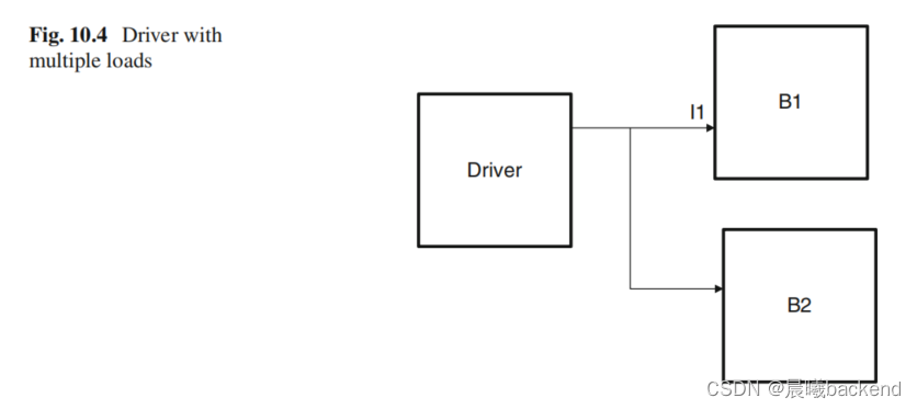
- 对于电路单元B1的输入引脚I1,可以指定驱动单元。如果需要更精确地控制特定的弧,我们也可以指定其他选项**(-library、-pin、-from_pin)。**
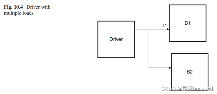
- 整个驱动能力不只驱动输入引脚I1,还驱动另一个引脚(在B2上)。所以,用于I1的有效驱动能力需要被划分,这时可以使用开关-mulitiply_by达到这种效果。但是,通常使用set_load命令实现这种效果,这部分内容将会在本章10.6.5节讲解。
10.2.1.7 Scaling
- 某种电气特性可能需要基于操作条件进行扩展,这种扩展的另外一种说法是降额。如果你不想使用扩展或降额特性,那么使用开关-dont_scale。
10.2.1.8 Design Rules
- 如果驱动引脚有设计规则属性(如能驱动的最大负载),那么这些属性会转移到输入端口。开关**-no_design_rule会防止属性转移到输入端口**。
10.2.1.9 Clock Association
set_input_delay -clock CLK1 3.0 [get_ports I1]
set_input_delay -clock CLK2 4.2 [get_ports I1] -add_delay
- Now, if we specify:
set_driving_cell BUF1 [get_ports I1]
it would mean that BUF1 will be used as a driver for both the above input_delay specifications.
However, if we were to specify:
set_driving_cell BUF1 -clock CLK1 [get_ports I1]
that would mean that the driving cell, BUF1 , would be used only for the fi rst input_delay specifi cation.
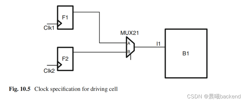
set_driving_cell -lib_cell MUX21 -from_pin A -clock CLK1 [get_ports I1]
set_driving_cell -lib_cell MUX21 -from_pin B -clock CLK2 [get_ports I1]
- 这样,源于CLK1的路径,从A到Z的弧(MUX21)作为驱动单元,源于CLK2的路径,从B到Z的弧也作为驱动单元。
10.2.1.10 Input Transition
- 可以使用-input_transiton_rise和-input_transiton_fall指定驱动单元MUX21输入A和B的上升和下降过渡时间,
- 这个上升和下降过渡时间将会影响MUX21,输出Z的过渡时间,这一点在电路单元B1的输入端可以看到。
10.2.1.11 Ports
- 设计者必须为已经使用的驱动单元属性指定端口列表。
- set_driving_cell命令最常用的选项是指定驱动单元的名称和指定驱动单元的端口。其他开关和选项都不经常使用,但它们会用在一些特殊情况下,目的是获得更好的控制,
10.3 Input Transition
- The commands set_drive and set_driving_cell are used by the tools to compute the transition time at the input port. However, a designer could specify the transition time directly. The SDC command for specifying the input transition time directly is:
set_input_transition [ -rise ] [ -fall ]
 [ -min ] [ -max ]
 [ -clock clock_name]
 [ -clock_fall ]
 transition port_list
- set_clock_transition和set_input_transition 的主要区别是set_clock_transition指定的过渡时间用于整个时钟网络.
- 用set_input_transition指定的过渡时间只用于特定端口
10.3.1 Input Transition Versus Clock Transition
- 如果使用set_clock_transition在clk端口指定过渡时间,那么在clk端口的扇出锥中所有触发器的时钟终端都使用相同的过渡时间。For all the nets in the network, namely, n1, n2, n3 , …, the same transition time would be assumed to be applicable.
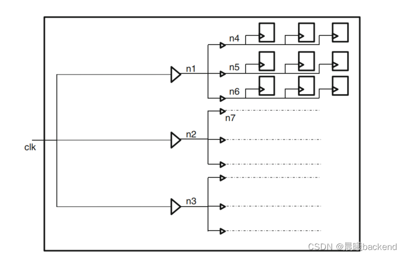
- 但是,如果使用set_input transition在clk端口指定过渡时间,那么,在每个节点即n1、n2、n3…都会计算过渡速度,包括所有触发器的时钟终端。
- A good usage of these two constructs is: Before the clock tree is routed, the clock net could be driving a huge fanout. Trying to compute the transition time on the clock net could result in a very very slow transitioning signal – due to a heavy load. So, in such cases, set_clock_transition should be used. It is expected that the clock tree synthesis will ensure that the transition rate on the clock network remains within a reasonable value.
- 一旦时钟树综合后,最好在所有节点上计算过渡时间值。Use of set_input_transition (instead of set_clock_transition ) at this stage will cause the timing analysis to compute the real transition value in the fanout cone of the clk port.
10.4 Fanout Number
set_port_fanout_number value port_list
- 它指定各种输出端口的扇出数,所以它是一个整数。
- 如果已知外部寄生负载并且已经指定了外部寄生负载(使用set_load命令指定,此命令会在10.6节中提到),那么这个命令没有具体含义。
10.5 Fanout Load
set_fanout_load value port_list
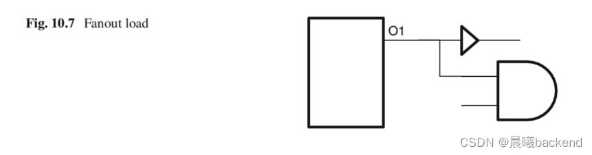
- 假设由缓冲器表现的负载是一个标准负载,与门的负载值是缓冲器负载值的1.5倍,即与门的负载就是标准负载的1.5倍。这样,端口O1的负载是标准负载的2.5倍。
- set_port_fanout_number是2, 因为这个端口驱动两个引脚
- 个实例解释了set_fanout_load和set_port_fanout_number的根本区别
10.6 Load—负载
- 当外部负载用标准负载表示时,工具把扇出值转换成了等效电容负载。表示外部负载的一个更常用的方法是直接指定外部电容值而不是扇出。
set_load [ -min ] [ -max ]
 [ -subtract_pin_load ]
 [ -pin_load ]
 [ -wire_load]
 value objects
- The -min/-max qualifiers have the usual meaning. The -min value is to be used during hold analysis, and the -max value is to be used during setup analysis.
10.6.1 Net Capacitance
- One of the most important things to note is that set_load can be applied even on wires, which are internal to the design under analysis. Thus, it provides a very convenient method to annotate extracted net capacitance obtained after post-layout.
- After the layout is done, effective net capacitance of each net can be extracted . And for the timing analysis tools, the capacitance value can be annotated on each net, through the set_load command. This allows net capacitance to be extracted by tools which are more accurate in extraction and used by STA tools.However, this switch should be specified only if the pin capacitances were also included during extraction. Most extraction tools will extract the net capacitance separately. If only that net capacitance is being annotated, this switch should not be specifed.
10.6.2 Pin Load Adjustments
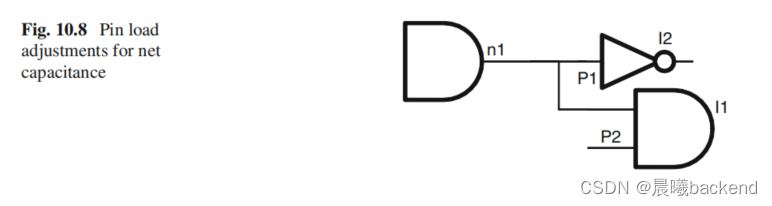
-
Let us say that during extraction of net capacitance for net n1, the extraction tool also included the loading of the pins I1/P2 and I2/P1. Now, this capacitive value gets annotated on the net n1.
-
The timing analysis tool sees the load on net n1 which it considers to be the wire load only and then adds the load due to pins, I1/P2 and I2/P1. So the load due to the pins gets counted twice.
-
So, in order to avoid double-counting, the switch -subtract_pin_load needs to be specifi ed while annotating net capacitance.
10.6.3 Load Type
- Whether the specifi ed load is of type pin or wire is specified using switches -pin_load or -wire_load . Tools might treat wire and pin loads differently. For example, slew might be degraded when propagating through wires. Let us consider the circuit in Fig. 10.9
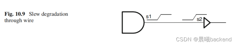
- The slew s1 at the output of the AND gate is computed based on the characteristics of the AND gate, the slew at the corresponding input pin of the gate and the load at the gate output.
- This signal then moves across the wire to the input of the buffer.
- However, as the signal travels across the wire, the slew characteristics get changed by the time it reaches the input of the buffer, so that the slew s2 at the buffer input is different from the original slew, s1 .
- This concept called slew degradation occurs for wires and not for pins.
10.6.4 Load Versus Fanout Load
- 电容负载(由set_load指定)=标准负载(由set_fanout_load指定)x单个标准负载的电容负载。
- 在早期,标准负载常常用于指定引脚负载,但是,现在的工艺库中很少用到标准负载。
10.6.5 Load at Input—输入负载
- 通常情况下,需要在输出端口指定负载。但是,有时也需要在输入端口指定负载。
- 对于电路单元B1的引脚I1,如果指定了驱动能力或驱动单元,并且相同驱动单元会看到额外的负载,那么引脚I1获取的有效驱动就减小了。这时,需要指定输入引脚I1的额外负载,以便调整有效驱动。
- 只要I1的驱动被指定为驱动能力(由set_drive指定)或者一个驱动单元(由set_driving_cell指定)那么就需要指定这个负载。如果为I1指定了输入过渡时间,那么对输入负载没有任何影响。
10.7 Conclusion
在设计早期,不知道驱动器的实际细节,所有模块都自底向上构建。在这个阶段,最好使用如set_input_transition等命令对输入过渡时间进行约束。
- 随着设计的进行,各种模块和顶层SoC被综合和可用时,我们就知道了实际的驱动单元。在这个阶段,我们可以使用set_driving_cell指定实际的驱动器和时序弧。
- 输出规格中较常用的命令是set_load。


 3013
3013


 被折叠的 条评论
为什么被折叠?
被折叠的 条评论
为什么被折叠?
 到【灌水乐园】发言


