


参考:中文参考手册 108页 M3与M4权威指南 321页

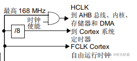
Systick时钟源有两个一个是HCLK(168MHZ)和8分频的HCLK(21MHZ)。
HCLK时钟频率参考时钟树
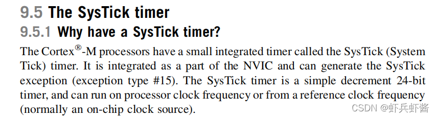
Cortex–M处理器有一个小型的集成计时器,称为SysTick(系统)计时器。它作为NVIC的一部分进行了集成,并可以生成SysTick异常(异常类型#15)。SysTick计时器是一个简单的24位递减计时器,可以在处理器时钟频率或参考时钟频率(通常是片上时钟源)上运行。
Systick是24位向下递减的计数器,中断由NVIC控制
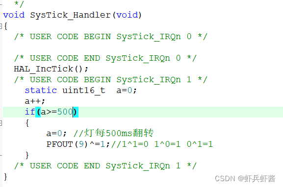
系统时钟中断的使用:
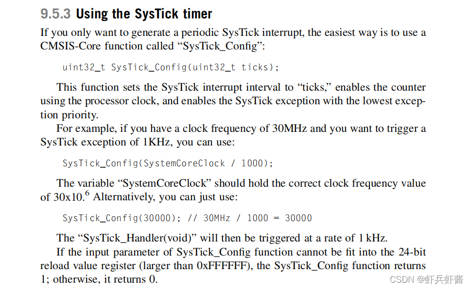
SysTick_Config()函数和中断服务函数SysTick_Handler(void)
注意 SysTick_Config()里的参数最大不超过24位(即16777215-1)
所以SYystick最大定时时间为T=1677214*1/168000000=99.86ms,不能超过它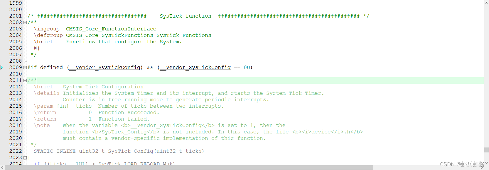 修改为:
修改为: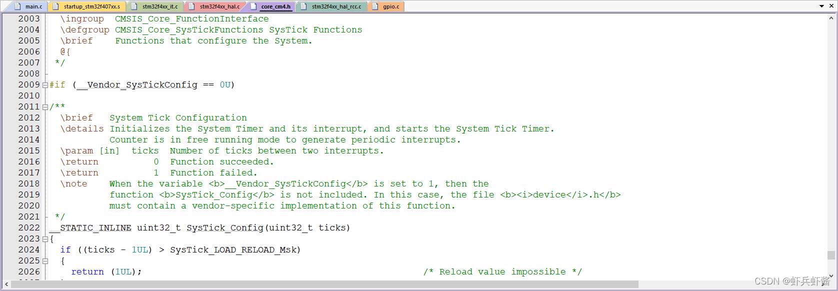
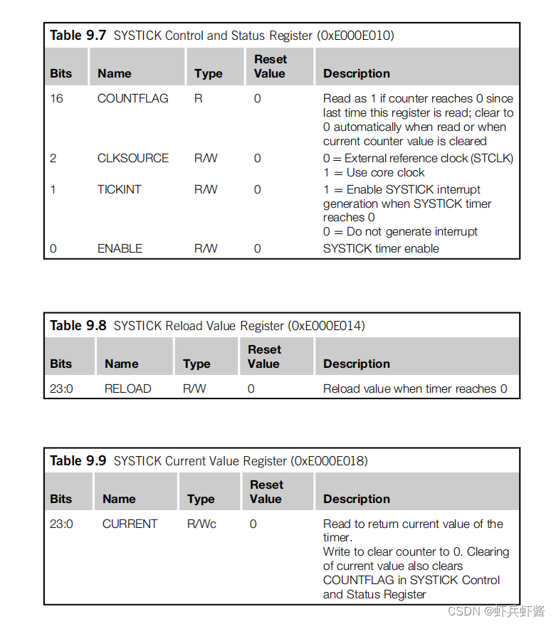
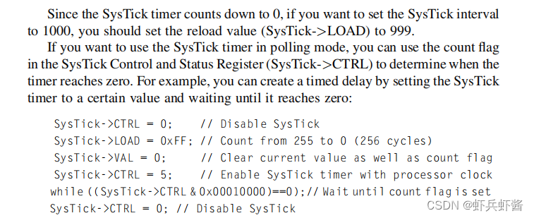
Systick延时使用使用寄存器:
参考M3与M4权威指南316
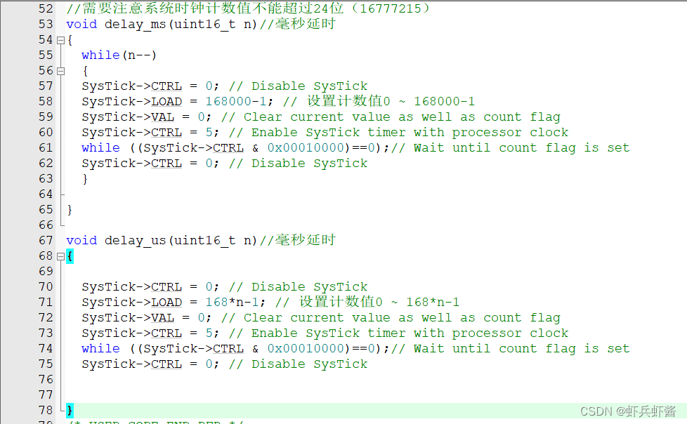
毫秒延时和微秒延时代码:
另外值得注意的是:hal库调用上面的函数需要勾选下面的选项,不然会卡在启动文件那里(具体原因不太清楚,希望评论区有大佬指点)


 1209
1209


 被折叠的 条评论
为什么被折叠?
被折叠的 条评论
为什么被折叠?
 到【灌水乐园】发言


