


Intelligent energy-saving control strategy for electric vehicle based on preceding vehicle movement
基于前车运动的电动汽车智能节能控制策略


abstract
In the existing driver assistance systems of electric vehicle, the vehicular forward radar is mainly used for active safety control and seldom for energy-saving control. In order to improve the energy efficiency of electric vehicle, this paper proposes a novel energysaving control strategy for electric vehicle based on movement of the preceding vehicle detected by forward radar. A hierarchical control architecture, which consists of three layers, is adopted in the proposed strategy. In the upper layer, the vehicles’ relative motion state is classified into four different scenarios based on the assessment of driving safety. In the middle layer, the energy-saving mode decision and transition control strategy are designed according to the scenario classification. In the bottom layer, the motor’s torque optimization and coordination control strategy are proposed to improve energy efficiency, while ensuring both driving safety and ride comfort. An optimized control algorithm based on Model Predictive Control (MPC) theory, is designed to optimize the motor’s torque for each mode in real-time. Finally, our proposed energy-saving control strategy is applied to an electric bus. Simulation and experiment tests are carried out to verify the effectiveness of the designed energy-saving control strategy. The results show that the proposed strategy can significantly reduce the energy consumption of electric vehicle under urban road conditions.
现有的电动汽车驾驶辅助系统中,车载前向雷达主要用于主动安全控制,很少用于节能控制。 为了提高电动汽车的能源效率,提出一种基于前向雷达检测前车运动的电动汽车节能控制策略。 该策略采用了由三层组成的分层控制架构。 在上层,根据行车安全评估,将车辆的相对运动状态分为四种不同的场景。 中间层根据场景分类设计节能模式决策和过渡控制策略。 在底层,提出了电机的扭矩优化和协调控制策略,以提高能源效率,同时保证行驶安全性和乘坐舒适性。 基于模型预测控制(MPC)理论的优化控制算法旨在实时优化每种模式下的电机扭矩。 最后,我们提出的节能控制策略应用于电动公交车。 通过仿真和实验测试验证了所设计的节能控制策略的有效性。 结果表明,所提出的策略能够显着降低城市道路条件下电动汽车的能耗。
1. Introduction
In recent years, new energy vehicles have received wide attention from both automobile manufacturers and researchers. Electric vehicles represent a promising solution to the depletion of fossil energy and vehicle emissions [1]. However, considering that the battery storage capacity of current electric vehicles is insufficient, the phenomenon where drivers are concerned about running out of power, or the so-called ‘range anxiety’, is a major obstacle for the widespread application and future advances of electric vehicles. Prolonging the driving range of electric vehicles has become a major challenge. Therefore, an effective energy-saving strategy is vital for improving the energy efficiency and driving range of electric vehicles.
近年来,新能源汽车受到汽车制造商和研究人员的广泛关注。 电动汽车是解决化石能源枯竭和车辆排放问题的一种有前途的解决方案[1]。 然而,考虑到目前电动汽车的电池存储容量不足,驾驶者担心没电的现象,即所谓的“里程焦虑”,是电动汽车广泛应用和未来发展的一大障碍。 汽车。 延长电动汽车的续驶里程已成为一项重大挑战。 因此,有效的节能策略对于提高电动汽车的能源效率和续驶里程至关重要。
Previous studies have shown that radical or aggressive driving operations such as rapid acceleration or rapid deceleration are high energy-consuming behaviors [2]. Therefore, vehicle speed optimization and optimal speed control are key research areas for energy-saving control. Barth et al. proposed a dynamic driving strategy, which used the location of the vehicle and the real time traffic information, including the average speed and service level of the section, to determine the speed of a specified vehicle, thus reducing the frequent acceleration or deceleration. Their results show that this strategy can reduce energy consumption by 10%–20% [3]. Grossard et al. designed an auxiliary driving system for electric vehicles with a similar method, which was to determine and provide the corresponding driving speed for the vehicle, also achieved an ideal energysaving effect [4]. Kuriyama and Miyatake introduced the optimal control model into the energy-saving driving assistant control. Under certain road and traffic conditions, the optimal control model was established with the total energy consumption as the planning goal. With this method, the optimal speed of vehicle at each moment is solved, thus the optimal speed curve is drawn to provide guidance for the vehicle running under certain conditions [5,6]. Mensing et al. took vehicle velocity and acceleration as control variables, and attained the energy-saving driving curve [7]. Laine et al. used control allocation to distribute the torque among different motors for maintaining vehicle motion and achieving energy-efficiency improvement [8]. Nandi proposed a comfortable and optimal driving strategy using a multi-objective optimization method [9]. A similar method was applied to hybrid electric vehicles or distributed electric vehicles and achieved multi-objective optimization [10–13]. As can be seen, energy-saving control strategy is one of the research hotspots in the field of electric vehicle. Despite the previous efforts, the dynamic time-varying information of traffic environment, such as the motion of the preceding vehicle, are not fully considered in these energy-saving control strategies. In addition, vehicular sensors in intelligent electric vehicle, such as forward radar, were not utilized in braking energy recovery of electric vehicle, so there is still potential for greater energy-savings.
以往的研究表明,快速加速或快速减速等激进或激进的驾驶操作是高耗能行为[2]。 因此,车辆速度优化和最优速度控制是节能控制的重点研究领域。 巴特等人。 提出了一种动态驾驶策略,利用车辆的位置和实时交通信息,包括路段的平均速度和服务水平,来确定指定车辆的速度,从而减少频繁的加速或减速。 他们的结果表明,这种策略可以减少 10%–20% 的能源消耗 [3]。 格罗萨德等人。 采用类似的方法设计了电动汽车辅助驱动系统,确定并为车辆提供相应的行驶速度,也取得了理想的节能效果[4]。 Kuriyama和Miyatake将最优控制模型引入到节能驾驶辅助控制中。 在一定的道路和交通条件下,以能源消耗总量为规划目标,建立最优控制模型。 该方法求解出车辆在每一时刻的最优速度,从而绘制出最优速度曲线,为车辆在一定条件下的运行提供指导[5,6]。 门辛等人。 以车辆速度和加速度为控制变量,得到节能行驶曲线[7]。 莱恩等人。 利用控制分配在不同电机之间分配扭矩,以维持车辆运动并实现能源效率的提高[8]。 Nandi 使用多目标优化方法提出了一种舒适且最优的驾驶策略[9]。 类似的方法应用于混合动力电动汽车或分布式电动汽车并实现了多目标优化[10-13]。 可见,节能控制策略是电动汽车领域的研究热点之一。 尽管之前的努力,这些节能控制策略并未充分考虑交通环境的动态时变信息,例如前车的运动。 此外,智能电动汽车中的车载传感器,如前向雷达等,并未用于电动汽车的制动能量回收,因此仍有较大的节能潜力。
With the development of Intelligent Transportation System (ITS) and communication technologies over the past few years, much attention has been paid to the energy-saving control of vehicles based on the traffic information, including the V2V and V2I communication, GIS and GPS, preceding vehicle movement, and road terrain profile. Information obtained from the ITS can be used to optimize vehicle control in terms of fuel efficiency [14], vehicle dynamic performance [15], and driving stability/safety [16].Chen et al. introduced an energy-efficient control strategy based on the preview of forward terrain profile to optimally distribute the torque between the front and rear motors as a method to save energy [17,18]. Zheng et al. presented a predictive driving control strategy for pure electric vehicles for energy saving [19]. Based on V2I technology, the optimal speed strategy for continuous intersections can help reduce energy consumption. Luo et al. proposes an optimal speed advisory method based on genetic algorithm, and the simulation results show that the proposed strategy has a significant advantage in reducing energy consumption and intersection passing time [20]. Based on V2V technology, the movement information of preceding vehicles was used to improve energy efficiency [21,22]. The Bayesian network was used to predict the future motion of the preceding vehicles and to optimize the speed and power output of electric vehicles [23–26]. However, the energy-saving effects of these technologies depend on external communication facility or device. The main drawback of existing energy-saving technologies is summarized as follows: The dynamic time-varying information of traffic environment, such as the motion of the preceding vehicle, is not fully considered. Although many recent studies have taken the preceding vehicle into account, they are too costly for their over-reliance on the external communication facility, and are difficult to be applied within a short period of time.
近年来,随着智能交通系统(ITS)和通信技术的发展,基于交通信息的车辆节能控制受到广泛关注,包括V2V和V2I通信、GIS和GPS等。 车辆运动和道路地形轮廓。 从 ITS 获得的信息可用于在燃油效率 [14]、车辆动态性能 [15] 和行驶稳定性/安全性 [16] 方面优化车辆控制。 引入了一种基于前方地形轮廓预览的节能控制策略,以优化前后电机之间的扭矩分配,作为节能的方法[17,18]。 郑等人。 提出了一种用于纯电动汽车节能的预测驾驶控制策略[19]。 基于V2I技术,连续交叉路口的最优速度策略有助于降低能耗。 罗等人。 提出一种基于遗传算法的最优车速咨询方法,仿真结果表明,该策略在降低能耗和路口通过时间方面具有显着优势[20]。 基于V2V技术,利用前车的运动信息来提高能源效率[21,22]。 贝叶斯网络用于预测前方车辆的未来运动并优化电动汽车的速度和功率输出[23-26]。 然而,这些技术的节能效果取决于外部通信设施或设备。 现有节能技术的主要缺点概括如下:没有充分考虑交通环境的动态时变信息,例如前车的运动。 尽管最近的许多研究都考虑了前车,但由于过度依赖外部通信设施,成本过高,且难以在短时间内得到应用。
In order to further explore the energy-saving potential of intelligent electric vehicles and seek a cost-effective method of improving energy efficiency based on existing vehicular sensor, we proposed an intelligent energy-saving controller (IEC) for electric vehicles in this paper. The main contribution of this paper is summarized as follows: We proposed an intelligent energy-saving control strategy for electric vehicle based on preceding vehicle movement detected by on-board radar originally used for active safety in vehicle. In order to achieve the objective of energy-saving for electric vehicle while considering both driving safety and driving intention, the IEC mode decision and transition control strategy are designed according to the classification of driving scenarios. In order to optimize the motor’s torque in each mode real-timely, an optimized control algorithm based on model predictive control (MPC) theory is designed. The proposed method fully considers the objectives of energy efficiency, driving safety and driving intention, and ensures the real-time performance of IEC.
为了进一步挖掘智能电动汽车的节能潜力,寻求一种基于现有车辆传感器的、经济有效的提高能源效率的方法,本文提出了一种电动汽车智能节能控制器(IEC)。 本文的主要贡献总结如下:我们提出了一种基于车载雷达检测前车运动的电动汽车智能节能控制策略,该策略最初用于车辆的主动安全。 为了在兼顾驾驶安全和驾驶意图的同时实现电动汽车节能的目标,根据驾驶场景分类设计了IEC模式决策和过渡控制策略。 为了实时优化电机各模式下的扭矩,设计了基于模型预测控制(MPC)理论的优化控制算法。 该方法充分考虑了能源效率、驾驶安全和驾驶意图等目标,并保证了IEC的实时性。
The remaining parts of this paper are organized as follows: The second section introduces the architecture of IEC system ased on preceding vehicle movement. The third section describes the energy-saving control strategy in detail. The fourth ection shows the results of simulation in Matlab/Simulink environment. The fifth section gives the results of the experiments to validate the effectiveness of our proposed IEC system. Finally, conclusions are drawn in the sixth section.
本文的其余部分组织如下:第二部分介绍了针对前行车辆运动的IEC系统的体系结构。 第三部分详细介绍了节能控制策略。 第四部分展示了Matlab/Simulink环境下的仿真结果。 第五部分给出了验证我们提出的 IEC 系统有效性的实验结果。 最后,第六部分得出结论。
2. Architecture of IEC system
The hierarchical control architecture in [27] is adopted in IEC system, which consists of three layers, as shown in Fig. 1.
IEC系统采用[27]中的分层控制架构,由三层组成,如图1所示。
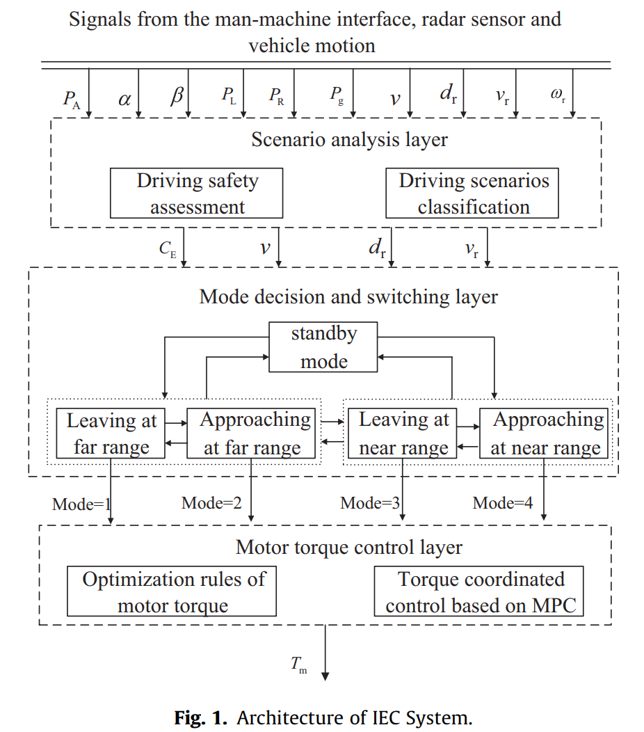
The upper layer is the scenario analysis layer, in which the driving safety is assessed based on the relative movement of ego-vehicle and preceding vehicle. The safe distance and working range of IEC are defined as the bases for scenario classification. In addition, the driver’s intention is recognized according to factors including the IEC switch, current gear position, acceleration pedal stroke, brake pedal stroke, cornering lamp, and yaw rate of the vehicle. The driving intention is used to determine whether the IEC should be open or exited.
上层为场景分析层,根据本车与前车的相对运动来评估行车安全。 IEC定义的安全距离和工作范围作为场景分类的基础。 此外,还根据IEC开关、当前档位、加速踏板行程、制动踏板行程、转向灯和车辆横摆率等因素来识别驾驶员的意图。 驾驶意图用于确定是否应该打开或退出IEC。
In the middle layer, we develop the mode decision and transition control strategy. According to the relative distance and velocity of ego-vehicle and preceding vehicle obtained from the radar, the driving scenario is classified into four states: leaving at far range, approaching at far range, leaving at near range and approaching at near range, where the demarcation of far range and near range is the safe distance. These four states correspond to four energy-saving modes respectively. The mode transition is carried out according to the motion state of ego-vehicle and preceding vehicle.
在中间层,我们开发模式决策和转换控制策略。 根据雷达获取的本车与前车的相对距离和速度,将驾驶场景分为远距离开、远距接近、近距离开和近距接近四种状态,其中 远距离和近距离的分界线就是安全距离。 这四种状态分别对应四种节能模式。 根据本车和前车的运动状态进行模式转换。
The bottom layer is the torque control layer, in which the optimization rule and coordinated control algorithm are designed to optimize the motor torque in each mode. The optimized control algorithm based on MPC method is designed to achieve the objective of energy efficiency, driving safety and ride comfort. The optimization rule of motor torque is designed to optimize the torque and increase braking energy recovery in different modes. The proposed method is supposed to guarantee the real-time performance of IEC.
最底层是扭矩控制层,设计优化规则和协调控制算法来优化各模式下的电机扭矩。 设计基于MPC方法的优化控制算法,以实现能源效率、行驶安全性和乘坐舒适性的目标。 设计电机扭矩优化规则,优化不同模式下的扭矩,增加制动能量回收。 该方法旨在保证IEC的实时性。
3. Energy-saving control strategy
3.1. Mode decision and transition control strategy based on scenario analysis
3.1.1. The classification of driving scenarios based on assessment of driving safety
The assessment of driving safety is an important basis for scenario classification and also a prerequisite for mode decision. Time Headway (THW) is adopted to assess the levels of driving safety in this paper. THW is defined as the time spacing between the two vehicles passing through the same place, and represents the maximum reaction time of the ego-vehicle driver when the preceding vehicle has an emergency brake. The model of minimum safe spacing based on THW is presented as
驾驶安全评估是场景分类的重要依据,也是模式决策的前提。 本文采用车头时距(THW)来评估行车安全水平。 THW定义为两辆车经过同一地点的时间间隔,代表本车驾驶员在前车紧急制动时的最大反应时间。 基于THW的最小安全间距模型为

Considering the driver’s pre-warning time and braking deceleration, the model of minimum safe spacing is established as
考虑驾驶员预警时间和制动减速度,建立最小安全间距模型为

Considering the emergency braking of the preceding vehicle, the model of safe spacing between the two vehicles is established as
考虑前车紧急制动,建立两车安全间距模型为

In order to ensure the driving safety, the safe distance ds should be the largest value amongst (1)–(3) and is expressed as
为了保证行车安全,安全距离
d
s
d_s
ds 应取式(1)~(3)中的最大值,表达式为

Similarly, the working range model of IEC is established as
类似地,建立IEC的工作范围模型为

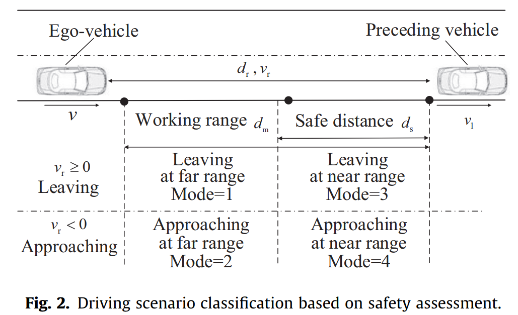
According to the safe distance and the working range obtained from Eq. (4) and Eq. (5), the driving scenario is classified into four states: leaving at far range, approaching at far range, leaving at near range and approaching at near range. These four scenarios correspond to four modes respectively, as shown in Fig. 2.
根据公式 (4) 和公式 (5)得出安全距离和工作范围,将驾驶场景分为四种状态:远距离离开、远距离接近、近距离离开和近距离接近。 这四种场景分别对应四种模式,如图2所示。
3.1.2. Mode transition control based on scenarios classification
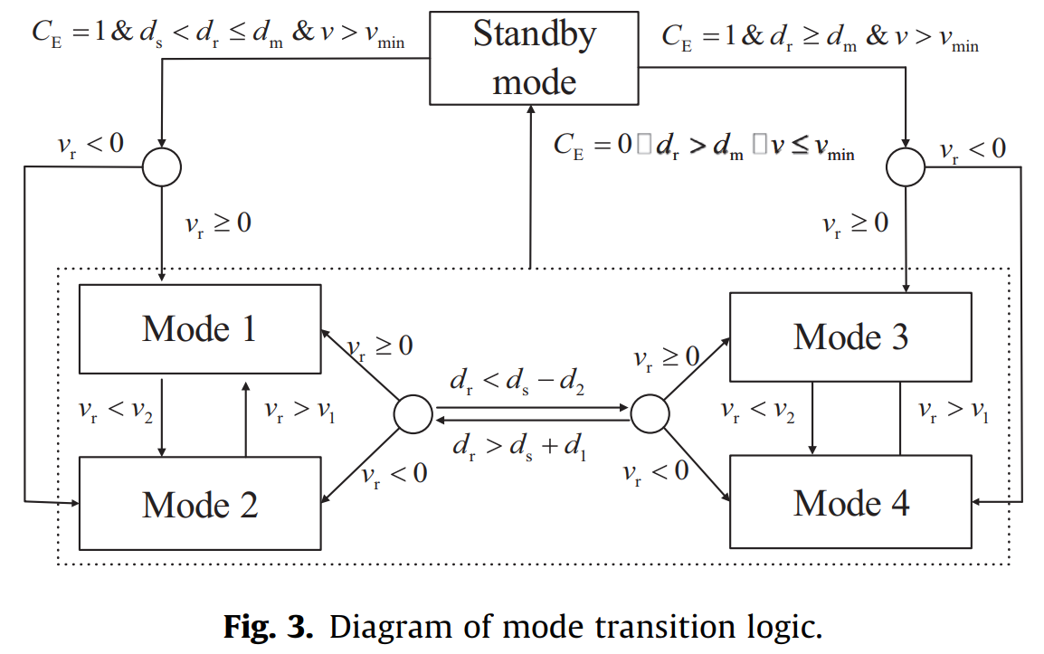
As shown in Fig. 3, the logical relationship of mode transition is established based on the scenarios classification. The condition that distinguishes a far-range scenario from a near-range scenario is dr > ds. However, to prevent frequent transition, a buffer zone is introduced to the actual transition condition. When dr > ds þ d1, the far-range modes, including mode 1 and mode 2, are switched to the near-range modes, including mode 3 and mode 4. When dr < ds d2, the far-range modes are switched to the near-range modes. Similarly, when vr > v1, the approaching modes, including mode 2 and mode 4, are switched to the leaving modes, including mode 1 and mode 3. When vr < v2, the leaving modes are switched to the approaching modes.
如图3所示,根据场景分类建立模式转换的逻辑关系。 区分远距离场景和近距离场景的条件是
d
r
>
d
s
d_r > d_s
dr>ds。 然而,为了防止频繁转换,在实际转换条件中引入了缓冲区。 当
d
r
>
d
s
+
d
1
d_r > d_s + d_1
dr>ds+d1 时,从远距离模式(包括模式1和模式2)切换到近距模式(包括模式3和模式4)。当
d
r
<
d
s
−
d
2
d_r < d_s - d_2
dr<ds−d2 时,从远距离模式切换到近距离模式。 类似地,当
v
r
>
v
1
v_r > v_1
vr>v1 时,为接近模式(包括模式2和模式4),当
v
r
<
v
2
v_r < v_2
vr<v2 时,将远离模式切换为接近模式(包括模式1和模式3)。
3.1.3. Open and Exit of IEC based on driving intention
The prerequisite and principles to be followed by IEC include: accounting for driver’s intention, not interfering with driver’s operation, and guaranteeing the driving safety. Thus, whether to activate the IEC depends on the driver’s intention and the state of the ego-vehicle. The driver’s intention can be identified by the IEC switch position, acceleration pedal stroke, brake pedal stroke and switch position of steering indicator lamp. The state of ego-vehicle contains current gear position, vehicle speed, yaw rate, system fault information, and etc. In order to meet the driver’s intention, the IEC will exit when its switch is turned off, the transmission gear is placed in the non-forward position, or the accelerator pedal stroke is larger than the set threshold. To prevent interference with the driver’s operation and to ensure driving safety, the IEC will exit when the cornering lamp is active, the vehicle is turning or changing lane, or a fault occurs. Thus, the formula of opening and exiting the IEC system is established as
IEC遵循的前提和原则包括:考虑驾驶员意图、不干扰驾驶员操作、保证行车安全。 因此,是否激活 IEC 取决于驾驶员的意图和自我车辆的状态。 驾驶员的意图可以通过IEC开关位置、加速踏板行程、制动踏板行程和转向指示灯开关位置来识别。 自车状态包含当前档位、车速、横摆率、系统故障信息等。为了满足驾驶员的意图,IEC在其开关关闭时会退出,变速器档位置于自动档位。 非前进位置,或油门踏板行程大于设定阈值。 为防止干扰驾驶员操作,确保行车安全,当转弯灯亮、车辆转弯或变道或发生故障时,IEC将退出。 由此,建立了打开和退出IEC系统的公式为

3.2. Control method of motor’s torque
In order to guarantee the real-time performance while considering the optimality of control, an optimized torque control algorithm combining optimization rules with MPC method is proposed. Based on the relative motion between the egovehicle and the preceding vehicle, the torque’s optimization rules in each mode are designed. The MPC algorithm is used to generate the optimization coefficients of the motor’s torque in each mode, and the motor torque is optimized realtimely with the proposed method.
为了在保证实时性的同时考虑控制的最优性,提出了一种将优化规则与MPC方法相结合的优化转矩控制算法。 基于本车与前车的相对运动,设计了各模式下的扭矩优化规则。 利用MPC算法生成各模式下电机扭矩的优化系数,并利用该方法实时优化电机扭矩。
3.2.1. Control algorithm of vehicle-following movement based on MPC
(1) Dynamic modeling of vehicle-following system
The dynamic model of vehicle-following system consists of the longitudinal dynamics model of the ego-vehicle and the relative motion kinematics model between the ego-vehicle and the preceding vehicle. The simplified model of vehicle’s longitudinal dynamics is presented as
跟驰系统动力学模型由本车纵向动力学模型和本车与前车相对运动运动学模型组成。 车辆纵向动力学简化模型为

When using the frequency response method [28] to identify the longitudinal dynamic characteristics of the vehicle, the following transfer functions can be obtained as
采用频率响应法[28]辨识车辆纵向动态特性时,可得到如下传递函数:

The kinematic relationship between the ego-vehicle and the preceding vehicle is shown as
本车与前车之间的运动学关系为

By integrating the relative motion kinematics model with the longitudinal dynamics model of the vehicles, a unified longitudinal dynamics model of the vehicle-following system can be established as
将相对运动运动学模型与车辆纵向动力学模型相结合,可以建立统一的跟驰系统纵向动力学模型:

The system state variable is defined as x ¼ ½dr;vr; aT, and the controlled variable is defined as u ¼ ades, then the longitudinal dynamics model of the vehicle-following system is shown as
系统状态变量定义为
x
=
[
d
r
,
v
r
,
a
]
T
x=[d_r,v_r,a]^T
x=[dr,vr,a]T,定义受控变量为
u
=
a
d
e
s
u=a_{des}
u=ades,则跟驰系统的纵向动力学模型为


represents interference input(代表干扰输入)。
Further, the equation of discretization can be obtained from (11) as
进一步,由(11)式可得离散化方程为


represent the coefficient matrix of discrete state equations, gðkÞ represents interference input at the current time.
表示离散状态方程的系数矩阵,
η
(
k
)
\eta (k)
η(k) 表示当前时刻的干扰输入。
When interference output is ignored, the system output is
当忽略干扰输出时,系统输出为

(2) Cost function and constraint condition design
The design objective of the vehicle-following control algorithm is driving safety, energy efficiency and ride comfort. Generally, the driver only responds to the large tracking deviation in the process of following the preceding vehicle, so the 2- norm is used to quantify the indexes [29]. The relative distance error and speed error are used as safety indexes. Let wd, wv represent weight coefficient of distance and velocity deviations respectively, then the objective of safety Lt is designed as
跟车控制算法的设计目标是行车安全、能源效率和乘坐舒适性。 一般情况下,驾驶员仅对跟随前车过程中较大的跟踪偏差做出反应,因此采用2-范数来量化指标[29]。 以相对距离误差和速度误差作为安全指标。 令
w
d
、
w
v
w_d、w_v
wd、wv 分别表示距离和速度偏差的权重系数,则安全目标
L
t
L_t
Lt 设计为

where, ddes ¼ s v þ d0 represents desired safe distance.
其中,
d
d
e
s
=
τ
⋅
v
+
d
0
d_{des}=\tau \cdot v + d_0
ddes=τ⋅v+d0 表示所需的安全距离。
Instantaneous energy consumption of EV increases with acceleration, so the longitudinal acceleration is used as energyefficiency index. Then the objective of energy efficiency Le is designed as
电动汽车的瞬时能耗随着加速度的增加而增加,因此采用纵向加速度作为能效指标。 则能量效率目标
L
e
L_e
Le 设计为

The objective of ride comfort depends on the driver’s feeling, which consists of the driver’s desired distance and longitudinal acceleration. Therefore, the constraint conditions are designed as
乘坐舒适性的目标取决于驾驶员的感觉,包括驾驶员期望的距离和纵向加速度。 因此,约束条件设计为


represent the minimum and maximum values of each parameter of the state variable.
表示状态变量的每个参数的最小值和最大值。
The linear weighted summation method is adopted to transform the multi-objective problem into a single-objective problem with various indexes. The cost function is shown as
采用线性加权求和的方法,将多目标问题转化为具有多种指标的单目标问题。 成本函数表示为

(3) Solution to the predicted problem
First of all, let k and i represent current time and predictive time increment respectively, then the predictive model of the ehicle-following system is established as
首先,令
k
k
k 和
i
i
i 分别表示当前时间和预测时间增量,则建立跟车系统的预测模型为

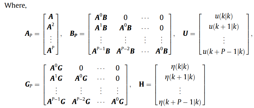
Without loss of generality, let P represent the length of predictive time domain, (18) can be described as
不失一般性,令P表示预测时域的长度,式(18)可描述为

Secondly, all cost functions in the predictive time domain are transformed into the predictive type by linear weighting, and the following results are obtained as
其次,将预测时域的所有代价函数通过线性加权转化为预测型,得到如下结果:

Thirdly, the constraint conditions are extended to the whole predictive time domain, and transformed into the predictive type. The equation (21) is thus obtained:
再次,将约束条件扩展到整个预测时域,转化为预测型。 由此得到式(21):

Finally, quadratic programming for predictive optimization problems is established from (19) and (20), as shown in Eq. (22), and this problem can be solved by Active Set Method [30].
最后,根据(19)和(20)建立了预测优化问题的二次规划,如式(19)所示。 (22),这个问题可以通过Active Set Method [30]来解决。

3.2.2. Optimization rules of motor’s torque in each mode
Optimization rules of motor’s torque is the key step of the IEC. The driving and braking torque of motor in each mode are optimized respectively to achieve energy-savings. In order to guarantee driving safety and fully consider the driving intention, different optimization rules for torque are formulated for different modes.
电机扭矩的优化规则是IEC的关键步骤。 电机在各模式下的驱动和制动扭矩分别进行优化,实现节能。 为了保证驾驶安全并充分考虑驾驶意图,针对不同模式制定了不同的扭矩优化规则。
In the standby mode, there is no restriction on the motor’s torque, where the originally required torque is the only output.
在待机模式下,电机的扭矩不受限制,仅输出原来需要的扭矩。

In far-range leaving mode, the maximum driving torque is partially limited to avoid unnecessary large accelerations. When the required torque is negative, the motor braking is added according to the driver’s deceleration intention and safety situation. The optimization rule of motor’s torque is presented as
在远距离离开模式下,最大驱动扭矩受到部分限制,以避免不必要的大加速度。 当所需扭矩为负时,根据驾驶员的减速意图和安全情况增加电机制动。 电机转矩优化规则为

where, Tmax and Tmin are the maximum driving torque and the maximum braking torque of the motor respectively whose values depend on the speed of the motor and the charge state of the battery pack.
其中,
T
m
a
x
T_{max}
Tmax 和
T
m
i
n
T_{min}
Tmin 分别是电机的最大驱动扭矩和最大制动扭矩,其值取决于电机的速度和电池组的充电状态。
The safety factor in far-range scenarios is defined as Cf ¼ ðdr dsÞ=ðdm dsÞ, to quantify the relative proximity of the two vehicles in a far-range scenario. KFD is the correction coefficient of driving torque in far-range modes, which is defined as function of Cf to reflect different limitation degrees of torque at different distances. KLB is the correction coefficient of braking torque in far-range modes, which is defined as function of Cf and brake pedal stroke b, to reflect different proportion of motor braking at different relative distances and braking intentions. When b ¼ 0, KLB becomes the coefficient of sliding brake torque. With the decreasing of relative distance, the braking torque is increased to improve the braking energy recovery.
远距离场景下的安全系数定义为
C
f
=
(
d
r
−
d
s
)
/
(
d
m
−
d
s
)
C_f=(d_r-d_s)/(d_m-d_s)
Cf=(dr−ds)/(dm−ds),以量化远距离场景下两辆车的相对接近程度。
K
F
D
K_{FD}
KFD 是远距离模式下驱动扭矩的修正系数,定义为
C
f
C_f
Cf 的函数,以反映不同距离下对扭矩的不同限制程度。
K
L
B
K_{LB}
KLB 是远距离模式下制动力矩的修正系数,定义为
C
f
C_f
Cf 和制动踏板行程
β
\beta
β 的函数,以反映不同相对距离和制动意图下电机制动的不同比例。 当
β
=
0
\beta = 0
β=0 时,
K
L
B
K_{LB}
KLB 成为滑动制动扭矩系数。 随着相对距离的减小,制动力矩增大,提高制动能量回收。
In far-range approaching mode, the maximum driving torque is partially reduced to avoid unnecessary large accelerations. Meanwhile, the changing rate of torque is limited to avoid rapid acceleration. When the required torque is negative, the motor braking is added in advance according to the driver’s deceleration intention and safety situation. The optimization rule of motor’s torque is presented as
在远距离接近模式下,最大驱动扭矩会部分降低,以避免不必要的大加速度。 同时,限制扭矩的变化率,避免快速加速。 当所需扭矩为负时,根据驾驶员的减速意图和安全情况提前添加电机制动。 电机转矩优化规则为

where, KTC represents coefficient of time to collision (TTC) defined as a piecewise linear function of TTC and is used to quantify the safety situation of driving. KAB represents the correction coefficient of braking torque in approaching modes, whose meaning is similar to KLB. To achieve more braking energy recovery, the value of KAB is designed to be larger than KLB. Tcr represents the limit of torque change rate, which is set according to the driving habits.
其中,
K
T
C
K_{TC}
KTC 表示碰撞时间系数(TTC),定义为TTC的分段线性函数,用于量化驾驶的安全状况。
K
A
B
K_{AB}
KAB 表示接近模式下制动力矩的修正系数,其含义与
K
L
B
K_{LB}
KLB 类似。 为了实现更多的制动能量回收,
K
A
B
K_{AB}
KAB 的值设计得比
K
L
B
K_{LB}
KLB 大。
T
c
r
T_{cr}
Tcr 代表扭矩变化率的极限,根据驾驶习惯设定。
In near-range leaving mode, the maximum driving torque and changing rate of torque output are partially limited to avoid unnecessary large and rapid accelerations. When the required torque is negative, the motor braking is added in advance according to the driver’s deceleration intention and safety situation. The optimization rule of motor’s torque is presented as
在近距离离开模式下,最大驱动扭矩和扭矩输出的变化率受到部分限制,以避免不必要的大而快速的加速。 当所需扭矩为负时,根据驾驶员的减速意图和安全情况提前添加电机制动。 电机转矩优化规则为

where, KND is the correction coefficient of driving torque in near range modes following a piecewise linear function consisting of Cn. Cn is safety factor in near range modes, which is defined as Cn ¼ dr=ds to quantify the relative proximity of two vehicles in near range modes. KND is used to reflect the different limitation degree of motor’s torque with different distance in near range modes. When Cn ¼ 1, KND is designed to be same as KFD, ensuring the seamless connection and smooth transition of the torque during the mode transition process. KTS represents coefficient of time to safe space (TTS) defined as a piecewise linear function of TTS and is used to quantify the driving safety in near range leaving scenario. TTS is defined as TTS ¼ ð Þ ds dr =vr.
其中,
K
N
D
K_{ND}
KND 是近距离模式下驱动扭矩的修正系数,遵循由
C
n
C_n
Cn 组成的分段线性函数。
C
n
C_n
Cn 为近距离模式下的安全系数,定义为
C
n
=
d
r
/
d
s
C_n = d_r/d_s
Cn=dr/ds,用于量化近距离模式下两辆车的相对接近程度。
K
N
D
K_{ND}
KND 用来反映近距离模式下不同距离电机扭矩的不同限制程度。 当
C
n
=
1
C_n=1
Cn=1 时,
K
N
D
K_{ND}
KND 设计与
K
F
D
K_{FD}
KFD 相同,保证模式转换过程中扭矩的无缝连接和平滑过渡。
K
T
S
K_{TS}
KTS 表示安全空间时间系数(TTS),定义为TTS的分段线性函数,用于量化近距离离开场景下的驾驶安全性。 TTS 定义为
T
T
S
=
(
d
s
−
d
r
)
/
v
r
TTS= (d_s-d_r)/v_r
TTS=(ds−dr)/vr。
In near-range approaching mode, the risk of collision is the largest of the four scenarios, so the power is directly cut off and switched to braking mode. Meanwhile, the motor braking is added in advance according to the driver’s deceleration intention and safety situation. The aforementioned design mechanisms are implemented to increase energy recovery while ensuring safety. The optimization rule of motor’s torque is presented as
近距离接近模式下,四种场景中碰撞风险最大,因此直接切断电源并切换至制动模式。 同时,根据驾驶员的减速意图和安全情况提前添加电机制动。 上述设计机制的实施是为了在确保安全的同时增加能量回收。 电机转矩优化规则为

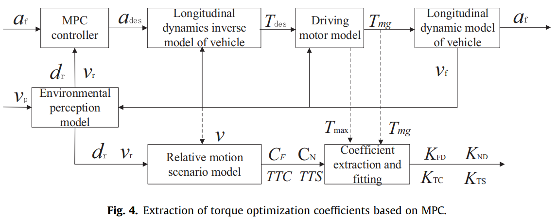
3.2.3. Extraction of torque optimization coefficients
The extraction of torque optimization coefficients is shown in Fig. 4. Based on the MPC algorithm, the MPC controller is established and integrated into a simulation platform for vehicle-following motion of electric vehicles. According to the relative motion between the ego-vehicle and the preceding vehicle, the model for relative motion scenario of the two-vehicle is established. The optimal torque can be calculated based on MPC, while considering both driving safety and energy efficiency. Then the optimization coefficients of motor’s torque can be extracted and fitted according to the relationship between the relative motion state of the vehicles and the optimal torque calculated by MPC controller.
扭矩优化系数的提取如图4所示。基于MPC算法,建立了MPC控制器,并将其集成到电动汽车跟车运动仿真平台中。 根据本车与前车的相对运动,建立两车相对运动场景模型。 基于MPC可以计算出最佳扭矩,同时考虑行车安全和能源效率。 然后根据车辆相对运动状态与MPC控制器计算出的最优扭矩之间的关系,提取并拟合电机扭矩的优化系数。
4. Simulation and analysis
4.1. Simulation platform
In this section, we present the simulation platform of electric vehicle developed in the Matlab/Simulink environment shown in Fig. 5.
在本节中,我们介绍在Matlab/Simulink环境中开发的电动汽车仿真平台,如图5所示。
The simulation platform is composed of four models: the driver model, the radar model, the IEC model and the vehicle model. The driver model is employed to simulate the driver operation and generate input signals to the controller. The radar model is used to simulate the relative velocity and distance of the preceding vehicle. The IEC model is established to calculate the control signals of the driving motor. The vehicle model contains the virtual bus model, VCU (vehicle controller unit) model, battery model, motor model, brake system model, final drive model and vehicle dynamic model, as shown in the dashed and rounded rectangular frame in Fig. 5. The vehicle dynamics model deals with the vehicle’s dynamic characteristics and is used to calculate the velocity and acceleration. This vehicle model, including its control strategies, has been tested on a real vehicle.
该仿真平台由四个模型组成:驾驶员模型、雷达模型、IEC模型和车辆模型。 驱动器模型用于模拟驱动器操作并生成控制器的输入信号。 雷达模型用于模拟前车的相对速度和距离。 建立IEC模型来计算驱动电机的控制信号。 车辆模型包含虚拟总线模型、VCU(车辆控制器单元)模型、电池模型、电机模型、制动系统模型、主减速器模型和车辆动力学模型,如图5虚线圆角矩形框所示。 车辆动力学模型处理车辆的动态特性,用于计算速度和加速度。 该车辆模型,包括其控制策略,已经在实车上进行了测试。
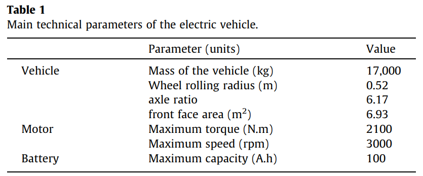
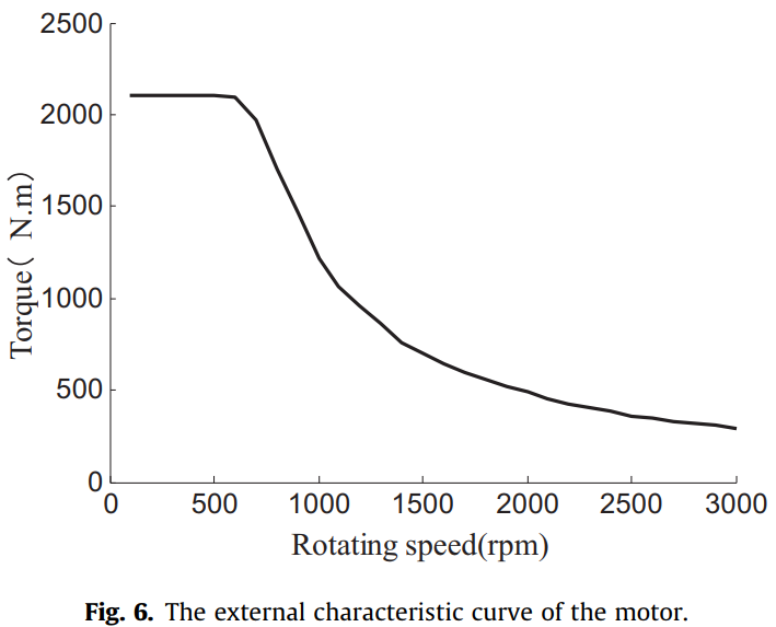
The main technical parameters of the vehicle are listed in Table 1, and the external characteristic curve of the motor is shown in Fig. 6.
整车主要技术参数如表1所示,电机外特性曲线如图6所示。
4.2. Simulation setting
To validate the effectiveness of the proposed control strategy, the Gipps driver model [31] is employed here to simulate the driver’s behavior. During the simulation, the parameters of the Gipps driver model are changed to simulate the different driving characteristics of the following behaviors.
为了验证所提出的控制策略的有效性,这里采用 Gipps 驾驶员模型 [31] 来模拟驾驶员的行为。 在仿真过程中,改变Gipps驾驶员模型的参数来模拟以下行为的不同驾驶特性。
4.2.1. Driving condition
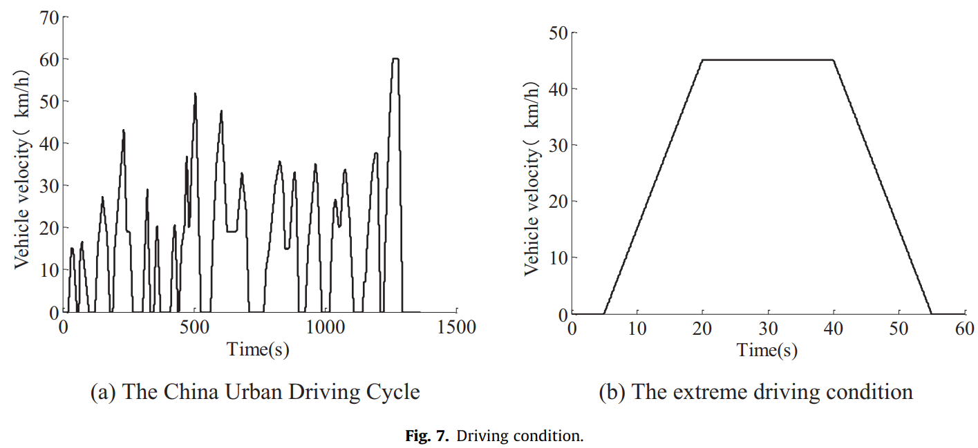
The China Urban Driving Cycle (CUDC) [32] is utilized to compare the energy consumption of the vehicle before and after the IEC switches on, as shown in Fig. 7(a). In order to analyze the profile of vehicle velocity and motor torque clearly, an extreme driving condition is designed, including a large acceleration and a large deceleration, as shown in Fig. 7(b).
利用中国城市驾驶循环(CUDC)[32]来比较 IEC 开启前后车辆的能耗,如 图7(a) 所示。 为了清楚地分析车辆速度和电机扭矩的变化曲线,设计了一个极端的行驶工况,包括大加速度和大减速度,如图 7(b) 所示。
4.2.2. Index of tracking capability and energy consumption
To reflect the tracking capability of control, the index S is defined in Eq. (28) by taking into account of both the velocity error and the distance error.
为了反映控制的跟踪能力,index S 定义为式(28)同时考虑速度误差和距离误差。

The energy consumption E can be calculated as
能量消耗 E 可计算为

4.3. Result and analysis
4.3.1. Result of the comparative statistics
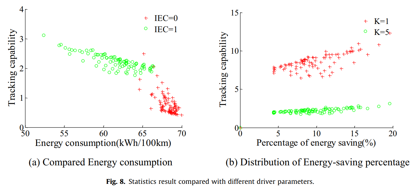
The energy consumption of electric vehicle was simulated in the Matlab/Simulink environment under the China Urban Driving Cycle. In order to show the energy-saving effect under different driving characteristics, 90 groups of simulations were ran based on different Gipps’ driver parameters. The comparative statistics are shown in Fig. 8, where IEC = 0 means the IEC is switched off while IEC = 1 means the IEC is switched on. Fig. 8(a) displays the results of energy consumption versus tracking ability based on different Gipps’ driver parameters. As can be seen from Fig. 8, the majority of cases are energyefficient when the IEC is turned on. Fig. 8(b) presents the results in percentage of energy-saving versus tracking ability based on different Gipps’ driver parameters and different weighting coefficients of the tracking capability. As is seen from Fig. 8, more than 4% of the energy-saving effect can be achieved when the IEC is open, and the average energy-savings percentage of the 90 groups of simulations is about 9.6%. The percentage of energy-savings between the techniques proposed in this research and research in [23] is compared, as shown in the Table 2.
在Matlab/Simulink环境下对中国城市工况下电动汽车的能耗进行了仿真。 为了展示不同驾驶特性下的节能效果,根据不同的 Gipps 驱动参数进行了90组仿真。 对比统计如图8所示,其中 IEC=0 表示 IEC 关闭,IEC=1 表示 IEC 开启。 图8(a) 显示了基于不同 Gipps 驱动器参数的能耗与跟踪能力的结果。 从图8可以看出,当 IEC 开启时,大多数情况都是节能的。 图8(b) 给出了基于不同 Gipps 驱动器参数和不同跟踪能力加权系数的节能百分比与跟踪能力的结果。 从图8可以看出,IEC 打开时可以达到4%以上的节能效果,90组模拟的平均节能百分比约为 9.6%。 本研究提出的技术与[23]研究的节能百分比进行了比较,如表2所示。

4.3.2. Analysis of result under CUDC condition
Fig. 9 shows the comparative results under the CUDC condition. Fig. 9(a) depicts the compared velocity profile of the vehicle before and after the IEC starts. Fig. 9(b) exhibits the time history of the compared energy consumption. The results show that the vehicle achieves less energy consumption when the IEC is switched on. Fig. 9© and (d) demonstrate the reason for less energy consumption. The motor’s torque achieves varying degrees of optimization according to the transition of IEC mode, as shown in Fig. 9(e), which leads to less energy consumption. The longitudinal acceleration of vehicle in the whole process is within a reasonable limit, as shown in Fig. 9(f). The compared tracking capability and energy consumption under this driving condition is shown in Table 3. Although the tracking capability decreases slightly, the energy consumption is reduced obviously. The percentage of energy-savings is about 7.1%.
图9所示为CUDC条件下的对比结果。 图9(a) 描绘了IEC启动前后车辆的速度曲线对比。 图 9(b) 显示了比较能耗的时间历史。 结果表明,当 IEC 开启时,车辆实现了更低的能耗。 图9 ( c) 和(d) 说明了能源消耗较少的原因。 电机的扭矩根据IEC模式的转变实现了不同程度的优化,如 图9(e) 所示,从而降低了能耗。 整个过程中车辆纵向加速度均在合理范围内,如 图9(f) 所示。 该驱动条件下的跟踪能力和能耗对比如 表3 所示。虽然跟踪能力略有下降,但能耗明显降低。 节能百分比约为7.1%。


4.3.3. Analysis of result under the extreme driving condition
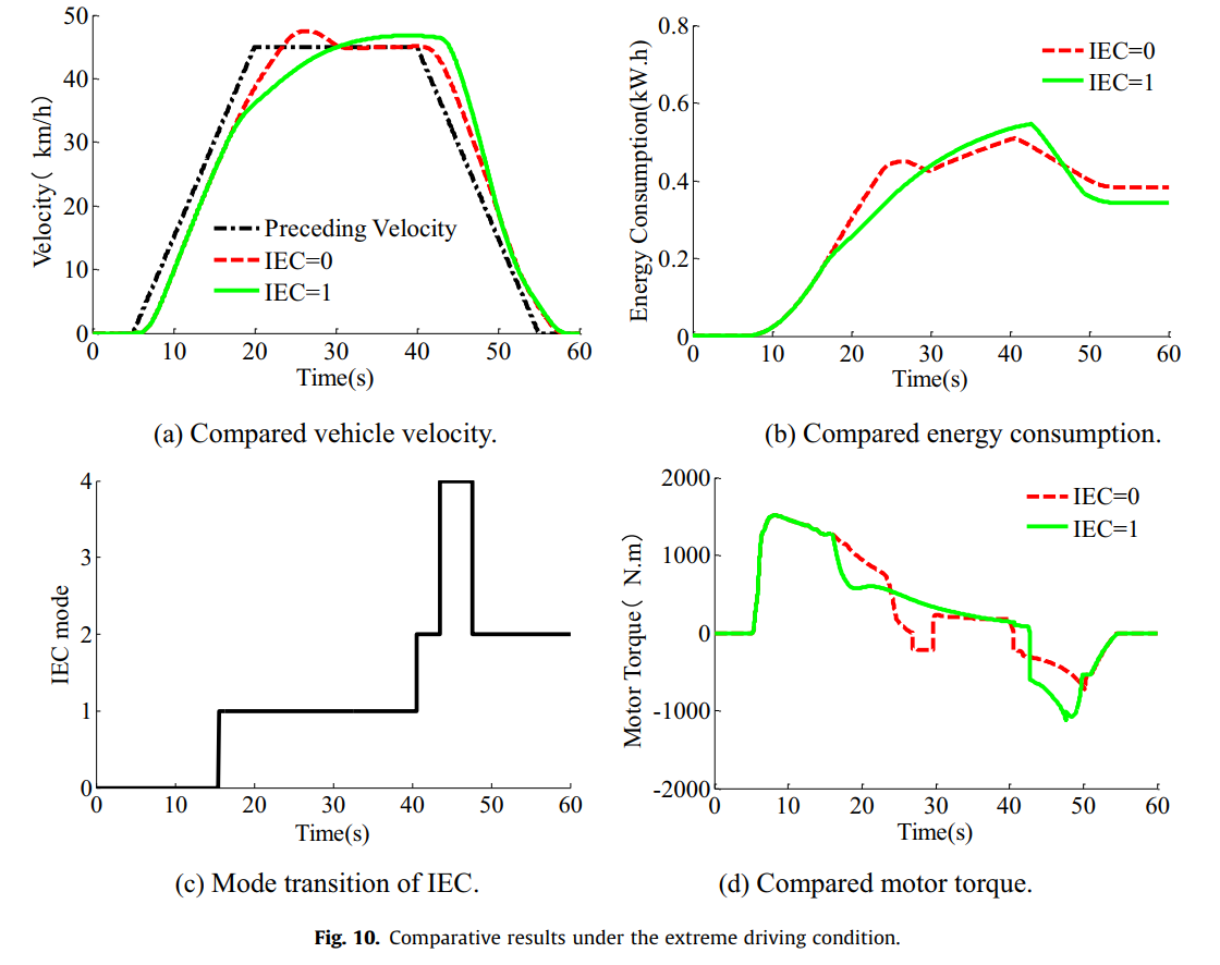
The energy consumption of electric vehicle was simulated in the Matlab/Simulink environment under an extreme driving condition with large acceleration and deceleration. Some detailed comparative results under this kind of driving condition are shown in Fig. 10. Fig. 10(a) presents the time history of vehicle velocity before and after the IEC starts in comparison with the preceding vehicle velocity. Fig. 10(b) depicts the time history of the compared energy consumption. The results show that the vehicle achieves less energy consumption when the IEC is switched on, which leads to poorer tracking performance. Fig. 10© and (d) illustrate the reasons for less energy consumption. Under this driving condition, the motor torque achieves varying degrees of optimization according to the swiching of IEC mode. As shown in Fig. 10(d), the driving torque of motor is reduced and the braking torque of motor is added, leading to less energy consumption. The compared tracking capability and energy consumption under this driving condition is shown in Table 4. The percentage of energy-savings is about 10.4%.
在Matlab/Simulink环境下对电动汽车在大加减速度的极端行驶工况下的能耗进行了仿真。 这种驾驶条件下的一些详细比较结果如图10所示。图10(a) 显示了IEC启动前后车速的时程与之前车速的比较。 图 10(b) 描述了比较能耗的时间历史。 结果表明,当IEC开启时,车辆的能耗较低,从而导致跟踪性能较差。 图10(c)和(d) 说明了能源消耗较少的原因。 在此驱动条件下,电机扭矩根据IEC模式的切换实现不同程度的优化。 如图10(d) 所示,减少了电机的驱动扭矩,增加了电机的制动扭矩,从而减少了能耗。 该行驶工况下的跟踪能力和能耗对比如表4所示,节能百分比约为10.4%。

5. Experimental verification
After the strategy development and simulation analysis, a rapid control prototype is developed based on a dSPACE MicroAutobox. Real vehicle experiments in the actual traffic environment were carried out on a pure electric vehicle to evaluate the control strategy.
经过策略开发和仿真分析,基于 dSPACE MicroAutobox 开发了快速控制原型。 在纯电动汽车上进行了实际交通环境下的实车实验,以评估控制策略。
5.1. Experimental setting
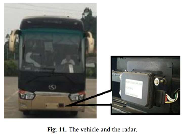
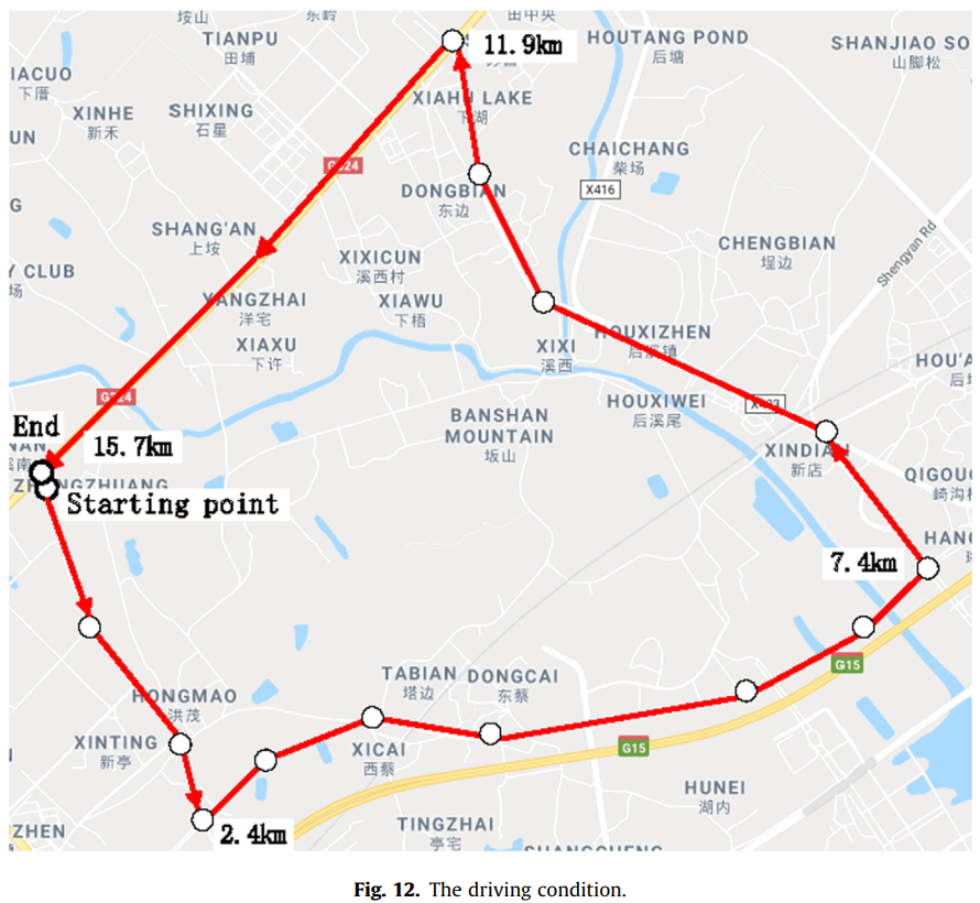
The test vehicle is a pure electric bus equipped with a forward radar, as shown in Fig. 11. The driving condition is an urban road containing a section of fast lane in Xiamen City located in the southern part of China, as shown in Fig. 12. The total length of the test road is about 15.7 km. Several groups of tests were carried out in order to compare and verify the effectiveness of the proposed IEC. Each group of test was implemented by the same driver with the IEC switched on and off respectively.
测试车辆为配备前向雷达的纯电动公交车,如 图 11 所示。行驶工况为位于中国南部的厦门市包含一段快车道的城市道路,如 图 12 所示试验道路总长约15.7公里。 为了比较和验证所提议的 IEC 的有效性,进行了几组测试。 每组测试均由同一驱动器在 IEC 分别打开和关闭的情况下进行。
5.2. Result and analysis
5.2.1. Result of the comparative statistics
7 groups of tests were carried out. The results of energy consumption are shown in Table 5. The vehicle’s average velocity is about 46 km/h. The average energy consumption is 73.1 kWh/100 km when the IEC is switched off and 68.8 kWh/100 km when the IEC is switched on. Affected by the time-varying traffic flow, the results of each test differ from each other. The average energy-savings percentage of the 7 test groups is about 5.9%.
共进行7组测试。 能耗结果如 表5 所示。车辆平均速度约为46 km/h。 IEC 关闭时平均能耗为 73.1 kWh/100 km,IEC 打开时平均能耗为 68.8 kWh/100 km。 受时变交通流的影响,每次测试的结果都存在差异。 7个测试组的平均节能百分比约为5.9%。

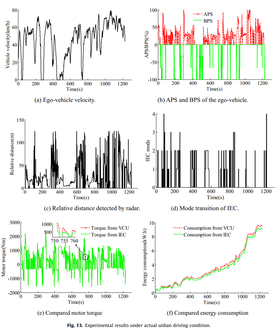
Fig. 13 shows one group of experimental result when the IEC is switched on. Fig. 13(a) and (b) depict respectively the time history of ego-vehicle velocity and the driver’s operation on the pedal, including acceleration pedal stroke (APS) and brake pedal stroke (BPS). It can be seen that the vehicle velocity is accordance with the driver’s intention on acceleration and deceleration. Fig. 13© depicts the relative distance to the preceding vehicle detected by the radar. With the change of relative distance and velocity, the mode transition of IEC works accordingly, as shown in Fig. 13(d). Fig. 13(e) depicts the respective motor torques from VCU and IEC. The peak of driving torque is partially reduced and the braking torque is added, which leads to less energy consumption as supported by Fig. 13(f). Since it is impossible to obtain the measured value of energy consumption of motor from VCU and IEC, the method of motor torque multiplied by motor speed is adopted to get the motor’s power. The energy consumption of the motor is reduced by 4.3% in this test.
图13为IEC开启时的一组实验结果。 图13(a)和(b) 分别描述了自车速度和驾驶员对踏板的操作的时间历史,包括加速踏板行程(APS)和制动踏板行程(BPS)。 可见,车辆速度与驾驶员的加减速意图一致, 图13(c) 描绘了雷达检测到的与前车的相对距离。 随着相对距离和速度的变化,IEC的模式转换也随之发生,如图13(d) 所示。 图 13(e) 描绘了来自 VCU 和 IEC 的各自电机扭矩。 驱动扭矩的峰值部分降低,制动扭矩增加,这导致能量消耗减少,如图13(f) 所示。 由于无法从VCU和IEC获得电机能耗的测量值,因此采用电机扭矩乘以电机转速的方法得到电机功率。 本次测试电机能耗降低4.3%。
5.2.2. Analysis of detailed results under a typical section of driving condition
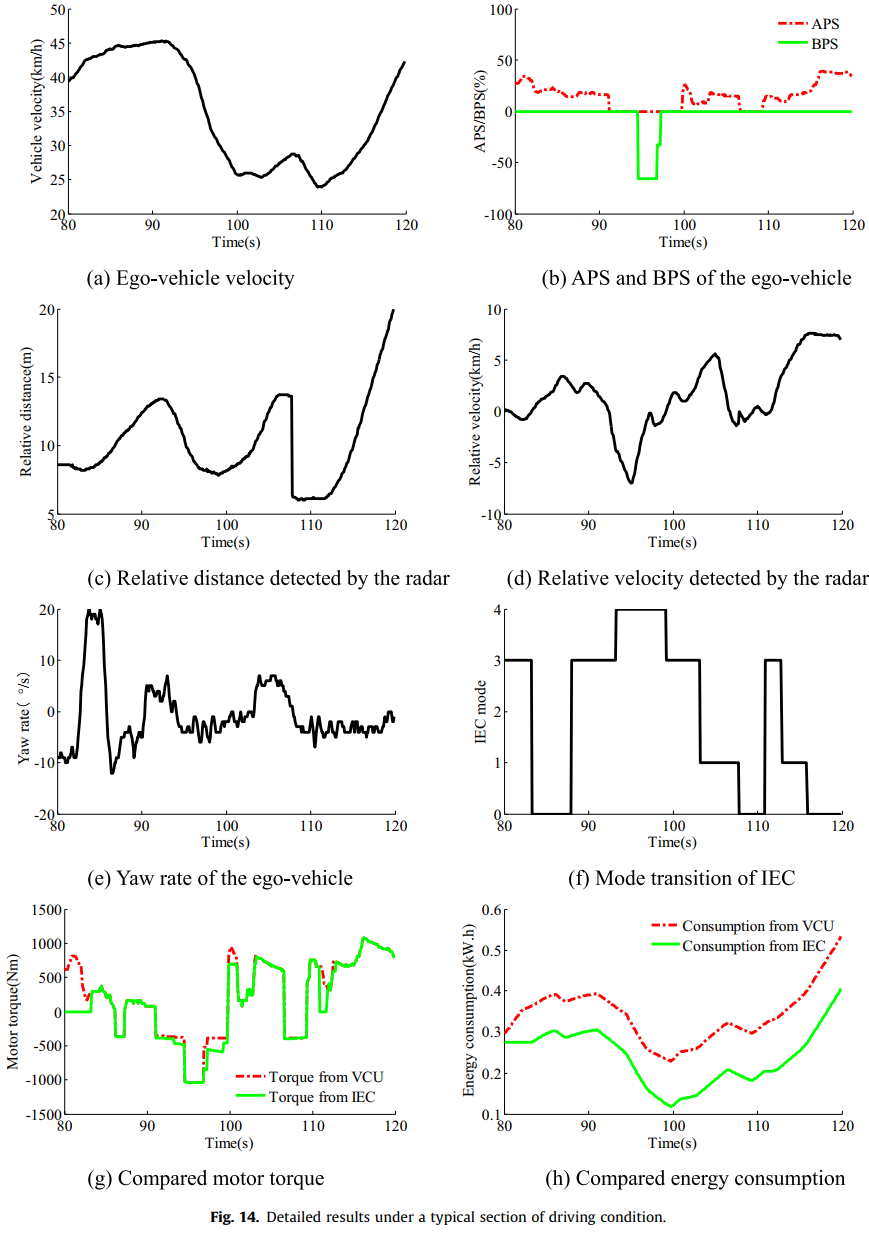
Fig. 14 shows the detailed results of one typical section of driving condition when the IEC is switch on. Fig. 14(a) and (b) depict respectively the time history of ego-vehicle velocity and the driver’s operation on the pedal. The vehicle velocity is consistent with the APS and BPS, which verifies that driving intentions are not disturbed. Fig. 14© and (d) depict the relative distance and velocity to the preceding vehicle detected by the radar. With the change of relative distance and velocity, the mode transition of IEC works accordingly, as shown in Fig. 14(f). When the yaw rate of ego-vehicle exceeds the threshold, which means changing lane or turning, the IEC switches to standby mode. Fig. 14(g) depicts the respective motor torques from VCU and IEC. The peak of driving torque is partially reduced and the braking torque is added at different degrees in different IEC modes, which leads to less energy consumption as supported by Fig. 14(h). From Fig. 14, it can be seen that the whole process is in accordance with the driver’s intention, and the velocity changes smoothly during the transition process.
图 14 显示了 IEC 开启时驱动条件的一个典型部分的详细结果。 图14(a)和(b) 分别描绘了自我车辆速度和驾驶员对踏板的操作的时间历史。 车辆速度与APS和BPS一致,验证了驾驶意图没有受到干扰。 图14(c)和(d) 描绘了雷达检测到的与前车的相对距离和速度。 随着相对距离和速度的变化,IEC的模式转换也随之发生,如图14(f) 所示。 当本车的横摆率超过阈值,即变道或转弯时,IEC切换到待机模式。 图 14(g) 描绘了来自 VCU 和 IEC 的各自电机扭矩。 在不同的IEC模式下,驱动扭矩的峰值被部分降低,制动扭矩被不同程度地增加,这导致了较低的能耗,如图14(h) 所示。 从图14可以看出,整个过程符合驾驶员的意图,过渡过程中速度变化平稳。
6. Conclusion
In this paper, the movement of the preceding vehicle detected by vehicular forward radar is adequately utilized to improve the energy efficiency of electric vehicle. According to the relative motion between the ego-vehicle and the preceding vehicle, four corresponding energy-saving modes and optimization strategies of motor’s torque are designed. Our proposed strategy achieves the expected energy-saving control by optimizing motor’s torque in different driving scenarios. The proposed energy-saving mode decision and transition control strategy based on the assessment of driving safety, guarantees both driving safety and driving intention. The proposed control algorithm used for motor’s torque optimization, which integrates optimization rules and MPC method, optimizes the motor’s power real-timely while ensuring both driving safety and ride comfort.
本文充分利用车载前向雷达检测到的前车运动来提高电动汽车的能量效率。 根据本车与前车的相对运动情况,设计了四种相应的节能模式和电机扭矩优化策略。 我们提出的策略通过优化不同驾驶场景下的电机扭矩来实现预期的节能控制。 提出的基于驾驶安全评估的节能模式决策和过渡控制策略,保证了驾驶安全和驾驶意图。 所提出的用于电机扭矩优化的控制算法,集成了优化规则和MPC方法,在保证行驶安全性和乘坐舒适性的同时,实时优化电机功率。
The simulation and experimental results proved the effectiveness of our proposed strategy. The energy-saving effectiveness is related to driving characteristics and traffic condition. The average energy-saving percentage of the 90 groups of simulations under CUDC condition is about 9.6%. The average energy consumption of the experimental bus under actual urban traffic condition is reduced by 5.9%.
仿真和实验结果证明了我们提出的策略的有效性。 节能效果与驾驶特性和交通状况有关。 CUDC条件下90组模拟的平均节能百分比约为9.6%。 实验公交车在城市实际交通条件下平均能耗降低5.9%。


 1008
1008

 被折叠的 条评论
为什么被折叠?
被折叠的 条评论
为什么被折叠?
 到【灌水乐园】发言


