


目录
4. 使用mmWave Demo Visualizer发送配置文件并观察检测结果
说明:之前使用AWR1642 ES1.0 EVM,只支持SDK1.2及以前的版本。在导入工程后进行rebuild的时候一直报错,在E2E论坛上也看了相关解答,原因无非是sdk版本太低。所以从现在开始改用AWR1843EVM。
这里首先给出总体的步骤流程,下面针对每一个步骤进行详细叙述。
1. 在CCS中导入过程并重新编译(先dss后mss)
2. 通过Uniflash烧写ccsdebug文件
3. 新建ccxml文件,连接EVM和CCS
4. 使用mmWave Demo Visualizer发送配置文件并观察检测结果
1. 在CCS中导入过程并重新编译(先dss后mss)
1.1 导入工程的步骤
- Go to menu Project -> Import CCS Projects.
- Next to Select search-directory, click Browse and browse to the location of a project OR if the project is available as an archive, then choose Select archive file and click on Browse to browse to archive.
- Select the desired project(s) from the list of Discovered projects.
- Leave the Copy projects into workspace option checked if you want to copy the projects into the workspace, otherwise uncheck the box. If unchecked, the project will continue to reside in its original location and all modifications/actions taken on the project will modify it in its original location.
导入之后如下图所示

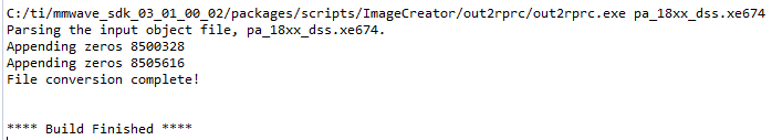
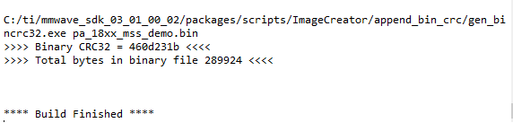
1.2 rebuild dss和mss工程
编译通过后会有如下信息。


2. 通过Uniflash烧写ccsdebug文件
步骤如下所示
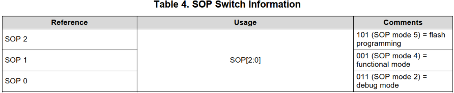
- 断电,将拨码开关设置为101,进入SOP mode 5 flash programming。
- 打开Uniflash,填写正确的COM口(Uart口,进入设备管理器即可查看)之后烧写文件xwr18xx_ccsdebug.bin,文件位于C:\ti\mmwave_sdk_<version>\packages\ti\utils\ccsdebug
- 烧写成功之后,断电,将拨码开关设置为001,进入SOP mode 4 functional model
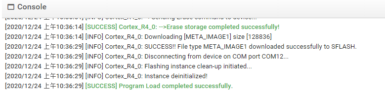
下图为AWR1843的SOP Switch Information和烧写成功之后的信息。
3. 新建ccxml文件,连接EVM和CCS
步骤如下所示
- 连接:新建ccxml文件,使用ccxml文件连接EVM板。先DSP后ARM
- 加载:加载编译生成的二进制文件:先DSP后ARM
- run:先ARM后DSP
图形化的操作步骤:


加载1.2小节编译生成的文件。


跑起来的信息如下所示,此时等待发送配置信息。

4. 使用mmWave Demo Visualizer发送配置文件并观察检测结果
运行自带的GUI程序,需要下载对应版本的MATLAB Runtime,下载地址。


 1万+
1万+


 被折叠的 条评论
为什么被折叠?
被折叠的 条评论
为什么被折叠?
 到【灌水乐园】发言


