Vulkan教程(12): Graphics pipeline Introduction (图形管线概要)

29 篇文章 2 订阅
10 篇文章 3 订阅

Vulkan官方英文原文:https://vulkan-tutorial.com/Drawing_a_triangle/Graphics_pipeline_basics/Introduction

对应的Vulkan技术规格说明书版本: Vulkan 1.3.2

Over the course of the next few chapters, we'll be setting up a graphics pipeline that is configured to draw our first triangle. The graphics pipeline is the sequence of operations that take the vertices and textures of your meshes all the way to the pixels in the render targets. A simplified overview is displayed below:

接下来的几个章节结束之后,我们会建立起一个图形管线,它被配置成能画出我们的第一个三角形。图形管线是一系列的有序操作(工作流):将模型网格上的顶点和纹理数据一直带到位于渲染目标中的像素。简化的流程图示如下:

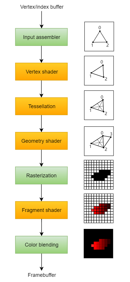
The input assembler collects the raw vertex data from the buffers you specify and may also use an index buffer to repeat certain elements without having to duplicate the vertex data itself.

输入装配器(input assembler) 从你指定的缓冲区中收集原始的顶点数据,也可能用一个索引缓冲区来重复收集特定元素而无需重复自身的顶点数据。

The vertex shader is run for every vertex and generally applies transformations to turn vertex positions from model space to screen space. It also passes per-vertex data down the pipeline.

顶点着色器(vertex shader) 是运行在每一个顶点上,通常用于从物体空间到屏幕空间变换顶点的空间位置。它也逐顶点地将数据沿着管线往下传。

The tessellation shaders allow you to subdivide geometry based on certain rules to increase the mesh quality. This is often used to make surfaces like brick walls and staircases look less flat when they are nearby.

细分着色器(tessellation shader)允许你基于一定的规则进一步细分几何体以提升模型网格的细节精度。像砖墙和楼梯,当它们靠近的时候,这个技术经常被用于产生表面细节使之看起来不那么平(看起来结构细节更多更真实)。

The geometry shader is run on every primitive (triangle, line, point) and can discard it or output more primitives than came in. This is similar to the tessellation shader, but much more flexible. However, it is not used much in today's applications because the performance is not that good on most graphics cards except for Intel's integrated GPUs.

几何着色器(geometry shader)是运行在每一个图元上(例如:三角形,线段,点),并且可以选择抛弃它或者输出比输入进来的图元更多的图元。这类似于细分着色器,但是更灵活。但是在当今的应用程序中它没有被大量使用,这是因为除了Intel集成显卡外在大多数显卡上它的性能没那么好。

The rasterization stage discretizes the primitives into fragments. These are the pixel elements that they fill on the framebuffer. Any fragments that fall outside the screen are discarded and the attributes outputted by the vertex shader are interpolated across the fragments, as shown in the figure. Usually the fragments that are behind other primitive fragments are also discarded here because of depth testing.

光栅化(rasterization)阶段将图元离散化为片段。这些片段是由一些像素元素组成的,他们填充整个帧缓冲区。任何片段落在屏幕外就被丢弃,(光栅化阶段)由顶点着色器计算输出的属性是片段间插值计算出来的。如上图所示。由于深度测试,通常在其他图元片段后面的片段也会被丢弃。

The fragment shader is invoked for every fragment that survives and determines which framebuffer(s) the fragments are written to and with which color and depth values. It can do this using the interpolated data from the vertex shader, which can include things like texture coordinates and normals for lighting.

片段着色器(fragment shader)应用于每个没有被丢弃的片段,并且决定片段将颜色和深度数据写入哪些帧缓冲区。片段着色器能利用顶点着色器插值计算得到的数据做到这些事情,其中可以包括像纹理坐标计算和用于光追的法线计算。

The color blending stage applies operations to mix different fragments that map to the same pixel in the framebuffer. Fragments can simply overwrite each other, add up or be mixed based upon transparency.

颜色混合(color blending)阶段应用混合不同片段的操作,这些被混合的片段是在帧缓冲区中的对应于相同像素的片段。这些片段可以简单地相互覆盖、叠加或者基于透明度混合。

Stages with a green color are known as fixed-function stages. These stages allow you to tweak their operations using parameters, but the way they work is predefined.

(上图中)绿色阶段被称作固定功能阶段。这些阶段允许你使用参数调整相关操作,但是其工作流程是预定义好的。

Stages with an orange color on the other hand are programmable, which means that you can upload your own code to the graphics card to apply exactly the operations you want. This allows you to use fragment shaders, for example, to implement anything from texturing and lighting to ray tracers. These programs run on many GPU cores simultaneously to process many objects, like vertices and fragments in parallel.

(上图中)红色阶段是可编程阶段,也就是说你可以将你的相关代码上传到显卡,以便准确的实现你想要的操作。例如,这就允许你使用片段着色器去实现纹理和光追光照的各自操作。这些程序在多个GPU计算单元同时运行,并行处理多个目标任务,例如并行执行多个顶点和片段操作。

If you've used older APIs like OpenGL and Direct3D before, then you'll be used to being able to change any pipeline settings at will with calls like glBlendFunc and OMSetBlendState. The graphics pipeline in Vulkan is almost completely immutable, so you must recreate the pipeline from scratch if you want to change shaders, bind different framebuffers or change the blend function. The disadvantage is that you'll have to create a number of pipelines that represent all of the different combinations of states you want to use in your rendering operations. However, because all of the operations you'll be doing in the pipeline are known in advance, the driver can optimize for it much better.

假如你以前用过像Opengl和DirectX3D这些旧的API,那么你需要调用像 glBlendFunc 和 OMSetBlendState 这类函数去改变渲染管线的设置。假如你想改变shader,绑定到不同的帧缓冲区或者改变混合功能,由于Vulkan中的图形管线几乎完全不可变,因此你必须从头新建一个管线。(这种机制的)缺点在于你必须创建一些管线,它们表示在你渲染操作中所需的各种不同的状态组合。但是,由于在管线中你要做的所有操作都事先知道,驱动程序可以把这些渲染过程优化的更好。

Some of the programmable stages are optional based on what you intend to do. For example, the tessellation and geometry stages can be disabled if you are just drawing simple geometry. If you are only interested in depth values then you can disable the fragment shader stage, which is useful for shadow map generation.

许多可编程阶段是依据你的需要可选择的。例如,如果你只是绘制基本的几何体,那么细分着色阶段和几何着色阶段可以被去掉。如果你只关心深度值(用于生成阴影贴图: shadow map),那你可以去掉片段着色阶段。

In the next chapter we'll first create the two programmable stages required to put a triangle onto the screen: the vertex shader and fragment shader. The fixed-function configuration like blending mode, viewport, rasterization will be set up in the chapter after that. The final part of setting up the graphics pipeline in Vulkan involves the specification of input and output framebuffers.

在下个章节,我们将首先创建两个可编程阶段,用于将三角形显示在屏幕上,这两个阶段是:顶点着色和片段着色。固定功能配置像混合模式、视口、光栅化这些设置在之后的章节细说。

Create a createGraphicsPipeline function that is called right after createImageViews in initVulkan. We'll work on this function throughout the following chapters.

创建一个 createGraphicsPipeline 函数,在 initVulkan 函数内部的 createImageViews 函数之后调用。

我们将在接下来的章节中使用这个函数。

void initVulkan() {
    createInstance();
    setupDebugMessenger();
    createSurface();
    pickPhysicalDevice();
    createLogicalDevice();
    createSwapChain();
    createImageViews();
    createGraphicsPipeline();
}

...

void createGraphicsPipeline() {

}

补充一些 Vulkan 的图形管线相关知识:

Dynamic State

请见:https://blog.csdn.net/vily_lei/article/details/128995011

Understanding vulkan objects: https://gpuopen.com/learn/understanding-vulkan-objects/

https://github.com/David-DiGioia/vulkan-diagrams

关于Vulkan Ray Tracing

注:TLAS是顶层加速结构,BLAS是底层加速结构。

Ray tracing in Vulkan consists of building acceleration structures, creating a ray tracing pipeline and shader binding table (SBT), and then tracing the rays with vkCmdTraceRaysKHR(...). There is also ray VK_KHR_ray_query for casting rays in existing shaders and does not require a ray tracing pipeline, but that is not discussed here.

Most of the work of building the acceleration structures is done by the driver, but the application developer is responsible for placing instances within a top-level acceleration structure (TLAS), grouping their primitives into bottom-level acceleration structures (BLASes) and within that BLAS grouping the primitives into geometries. How this is done can have a significant impact on performance. I've written an article on GPUOpen that goes into detail of best practices for ray tracing performance.

The first diagram shows the Vulkan objects needed to build a BLAS.

Note that almost no implementation supports VkPhysicalDeviceAccelerationStructureFeaturesKHR::accelerationStructureHostCommands so most likely you will need to build the acceleration structures on the device, as pictured in the diagrams. This makes compacting BLASes more complicated because it requires two queue submissions. The process to compact a BLAS is as follows:

Add VK_BUILD_ACCELERATION_STRUCTURE_ALLOW_COMPACTION_BIT_KHR flag to VkAccelerationStructureBuildGeometryInfoKHR::flags for original acceleration structure that is built.

Create original acceleration structure.

Create VkQueryPool with a VkQueryPoolCreateInfo::queryType of VK_QUERY_TYPE_ACCELERATION_STRUCTURE_COMPACTED_SIZE_KHR.

Query the compacted size with vkCmdWriteAccelerationStructuresPropertiesKHR(...).

Submit the command buffer then get the query results with vkGetQueryPoolResults(...).

Create a VkAccelerationStructureKHR with a VkBuffer with compacted size from query.

Start recording a new command buffer.

Copy the original acceleration structure to the compacted one using vkCmdCopyAccelerationStructureKHR(...) with VkCopyAccelerationStructureInfoKHR::mode set to VK_COPY_ACCELERATION_STRUCTURE_MODE_COMPACT_KHR.

Submit command buffer.

The next diagram shows the Vulkan objects needed to build a TLAS.

Lastly, the ray tracing pipeline and shader binding table.

  • 1
    点赞
  • 5
    收藏
    觉得还不错? 一键收藏
  • 0
    评论

“相关推荐”对你有帮助么?

  • 非常没帮助
  • 没帮助
  • 一般
  • 有帮助
  • 非常有帮助
提交
评论
添加红包

请填写红包祝福语或标题

红包个数最小为10个

红包金额最低5元

当前余额3.43前往充值 >
需支付:10.00
成就一亿技术人!
领取后你会自动成为博主和红包主的粉丝 规则
hope_wisdom
发出的红包
实付
使用余额支付
点击重新获取
扫码支付
钱包余额 0

抵扣说明:

1.余额是钱包充值的虚拟货币,按照1:1的比例进行支付金额的抵扣。
2.余额无法直接购买下载,可以购买VIP、付费专栏及课程。

余额充值