


错误的答案
module top_module(clk, reset, in, out);
input clk;
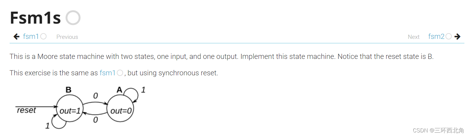
input reset; // Synchronous reset to state B
input in;
output out;//
reg out;
// Fill in state name declarations
//状态A为0,B为1
reg present_state, next_state;
initial
begin
present_state <= 0;
next_state <= 0;
end
always @(posedge clk) begin
if (reset) begin
present_state <= 1;
next_state <= 1;
end else begin
case (present_state)
// Fill in state transition logic
1'b0:begin
if(in == 1)
next_state<=0;
else
next_state<=1;
end
1'b1:begin
if(in == 1)
next_state<=1;
else
next_state<=0;
end
endcase
// State flip-flops
present_state = next_state;
case (present_state)
1'b0:out <= 0;
1'b1:out <= 1;
default:out <= 1;
endcase
end
end
endmodule
测试结果

正确的答案
// Note the Verilog-1995 module declaration syntax here:
module top_module(clk, reset, in, out);
    input clk;
    input reset;    // Synchronous reset to state B
    input in;
    output out;//
    reg out;

    parameter A = 0, B = 1; // Fill in state name declarations

    reg present_state, next_state;

    always @(posedge clk) begin
        if (reset) begin
            next_state = B;// Fill in reset logic
        end
        //描述状态转移条件
        else begin
            case (present_state)
                A: next_state = (in == 0) ? B : A;
                B: next_state = (in == 0) ? A : B;// Fill in state transition logic
            endcase
        end
 			//描述状态转移
            // State flip-flops
            present_state = next_state;
 		//描述状态输出
            case (present_state)
                A: out = 0;
                B: out = 1;// Fill in output logic
            endcase
        //end
    end

endmodule
这里的问题主要是两个部分:
-
错误程序中使用了非阻塞赋值语句,导致后面的赋值可能是并行执行的,因此状态不是顺序转换;
在三段式的状态机中,共有三个部分,即三段式:
三个always块,一个always模块采用同步时序描述状态转移;一个always采用组合逻辑判断状态转移条件,描述状态转移规律;第三个always块使用同步时序描述状态输出,寄存器输出。 -
倒数第三行的end应该在状态转移函数之后,模版有错误


 370
370


 被折叠的 条评论
为什么被折叠?
被折叠的 条评论
为什么被折叠?
 到【灌水乐园】发言


