


👨🎓个人主页:研学社的博客
💥💥💞💞欢迎来到本博客❤️❤️💥💥
🏆博主优势:🌞🌞🌞博客内容尽量做到思维缜密,逻辑清晰,为了方便读者。
⛳️座右铭:行百里者,半于九十。
📋📋📋本文目录如下:🎁🎁🎁
目录
💥1 概述
目前研究的四旋翼无人机航迹跟踪控制系统跟踪过程不稳定,导致跟踪结果不准确;为此基于MPC设计了一种新的四旋翼无人机航迹跟踪控制系统。通过空中飞行控制器、地面控制器和人工干预器实现了无人机航线的跟踪控制;空中飞行控制器包括GPS导航定位模块、姿态评估模块(MTI)、飞行控制系统计算机,显示模块等;地面控制器探测周围飞行环境,规避障碍物、规划安全航线,传输至空中自主飞行控制系统,包括无线通讯的数据连接电路和地面终端控制模块;人工干预模块能对飞行过程中发生的意外情况进行人工干预以避免突发情况造成危险。
📚2 运行结果
主函数部分代码:
%% Robot Motion Planning and Control Assignment
clc
clearvars
close all force
yalmip('clear')
%% Initialisation
Ts = 0.02; % sample time [s]
% Weighting matrices Q, Qt, R, W and control horizon N
mpc_sim.Q = [1e4 0 0 0 0 0;
0 1e2 0 0 0 0;
0 0 1e4 0 0 0;
0 0 0 1e2 0 0;
0 0 0 0 1e4 0;
0 0 0 0 0 1e2];
mpc_sim.Qt = mpc_sim.Q*1e2; % Terminal state matrix
mpc_sim.R = eye(3)*1e2; % Input matrix
mpc_sim.W = mpc_sim.Q; % Waypoint matrix
mpc_sim.N = ceil(2/Ts); % Control horizon [s]
%% Ring initialisation
% Ring 1
randx1 = -1+2*rand(1); % Generate x-coordinate for ring 1
randy1 = 1+3*rand(1); % Generate y-coordinate for ring 1
randz1 = -1+2*rand(1); % Generate z-coordinate for ring 1
% Ring 2
randx2 = -1+2*rand(1); % Generate x-coordinate for ring 2
randy2 = 5+4*rand(1); % Generate y-coordinate for ring 2
randz2 = -1+2*rand(1); % Generate z-coordinate for ring 2
%% Simulation settings
x0 = [0 0 0 0 0 0]'; % Define start position and velocity [m and m/s]
ring1 = [randx1 0 randy1 5 randz1 0]; % [x, desired x-velocity, y, desired y-velocity, z, desired z-velocity]
ring2 = [randx2 0 randy2 5 randz2 0]; % [x, desired x-velocity, y, desired y-velocity, z, desired z-velocity]
goal = [0 0 10 0 0 0]; % Define goal position and velocity [m and m/s]
simT = 7; % Simulation time [s]
ulim = [1 1 1]*7; % Maximum absolute value input [N]
%% Run simulations
% Run simulation and MPC controller. Inputs are simulation settings, start
% en goal positions, simulation time and sampling time, ring locations.
[results] = MPC_Controller(mpc_sim, x0, simT, Ts, ulim, ring1, ring2, goal);
%% Construct rings
t = linspace(0,2*pi);
x = cos(t);
y = sin(t);
z = 0*t;
pnts = [x;y;z];
n0 = [0;0;0.1];
n0 = n0/norm(n0);
n1 = [0;1;0];
n1 = n1/norm(n1);
c = dot(n0,n1) / ( norm(n0)*norm(n1) ); % cos(theta)
s = sqrt(0.1-c*c); % sin(theta)
u = cross(n0,n1) / ( norm(n0)*norm(n1) ); % rotation axis
u = u/norm(u); % unit rotation axis
C = 0.35-c;
% the rotation matrix
R = [u(1)^2*C+c, u(1)*u(2)*C-u(3)*s, u(1)*u(3)*C+u(2)*s
u(2)*u(1)*C+u(3)*s, u(2)^2*C+c, u(2)*u(3)*C-u(1)*s
u(3)*u(1)*C-u(2)*s, u(3)*u(2)*C+u(1)*s, u(3)^2*C+c];
% Rotated points
newPnts = R*pnts;
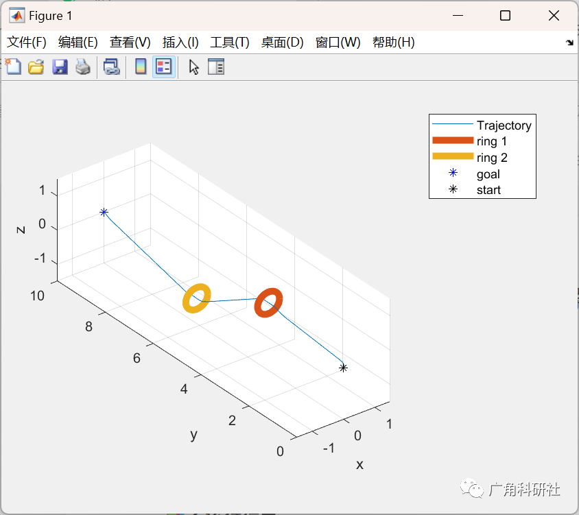
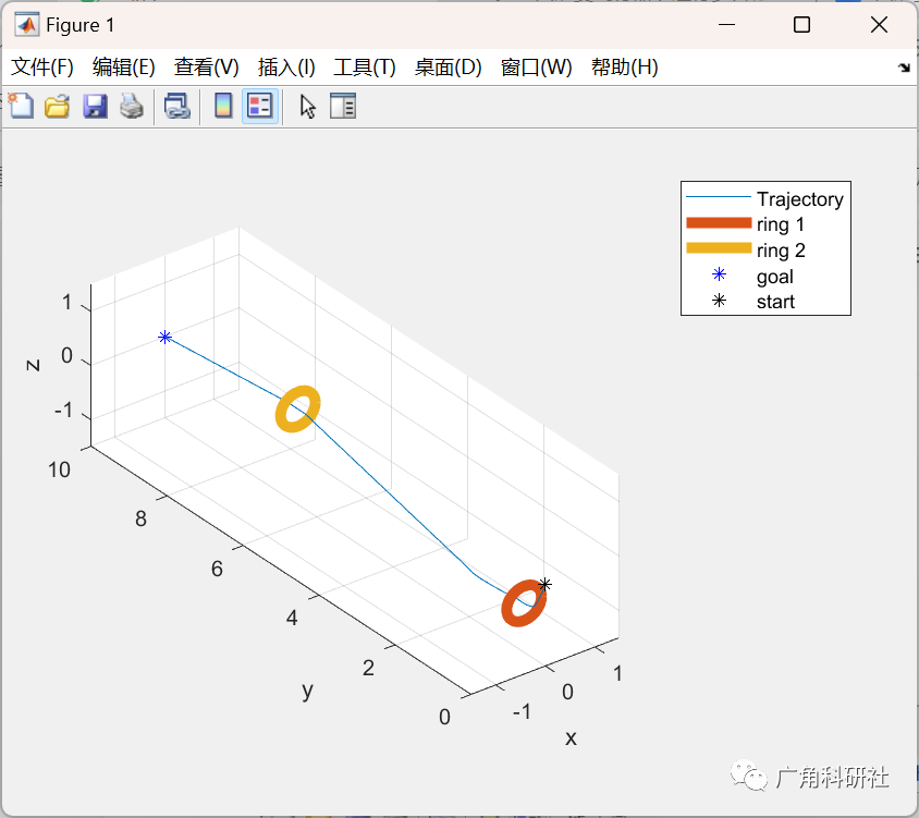
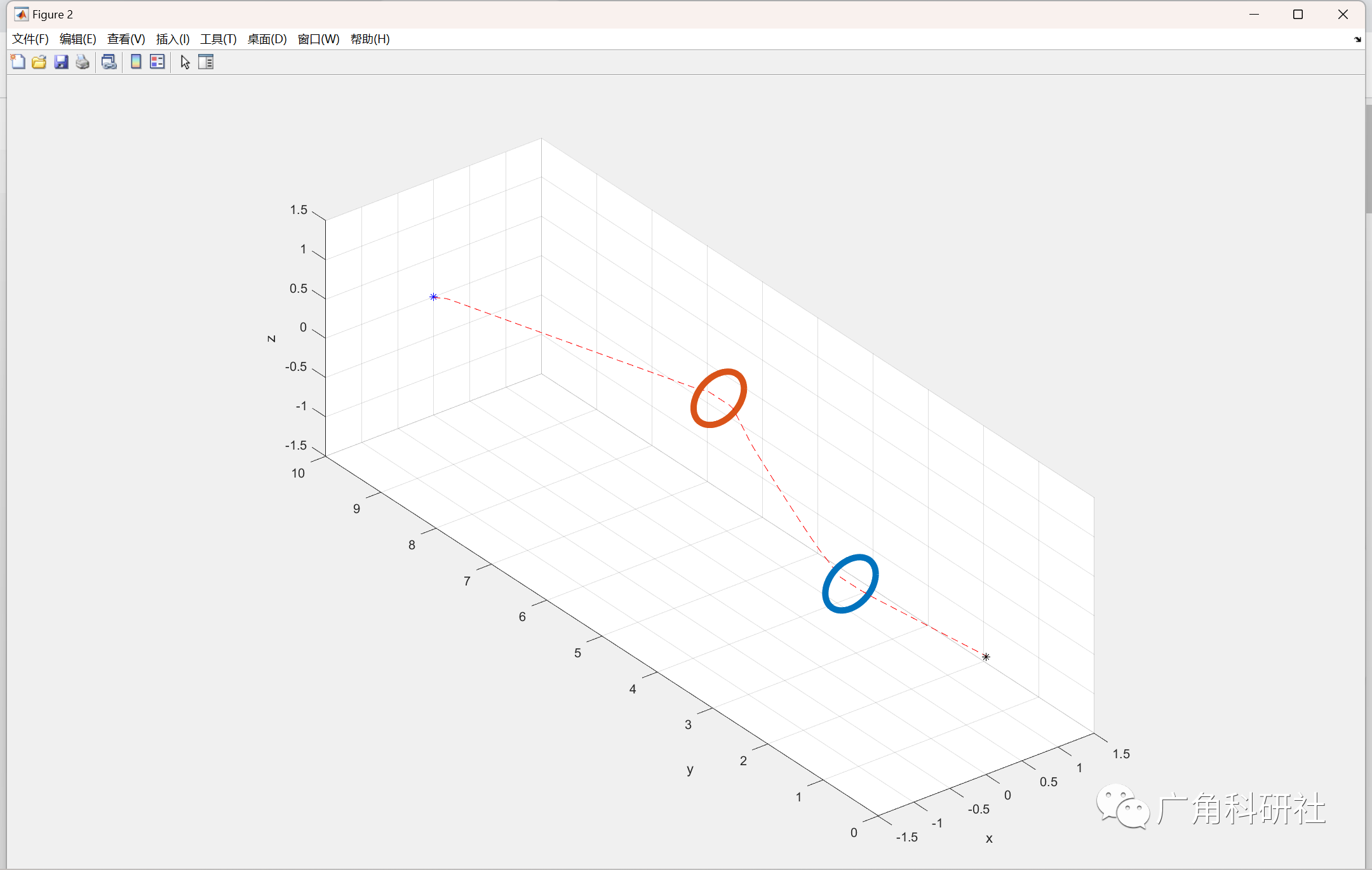
%% Plot results
figure; plot3(results.state(:, 1), results.state(:, 3), results.state(:, 5));
hold on
plot3(ring1(1)+1*newPnts(1,:), ring1(3)+1*newPnts(2,:), ring1(5)+1*newPnts(3,:), 'LineWidth',5)
plot3(ring2(1)+1*newPnts(1,:), ring2(3)+1*newPnts(2,:), ring2(5)+1*newPnts(3,:), 'LineWidth',5)
plot3(goal(1), goal(3), goal(5), 'b*')
plot3(x0(1), x0(3), x0(5), 'k*')
xlabel('x'); ylabel('y'); zlabel('z');
legend('Trajectory', 'ring 1', 'ring 2', 'goal', 'start')
grid on
xlim([-1.5 1.5]); ylim([0 10]); zlim([-1.5 1.5])
pbaspect([3 10 3])
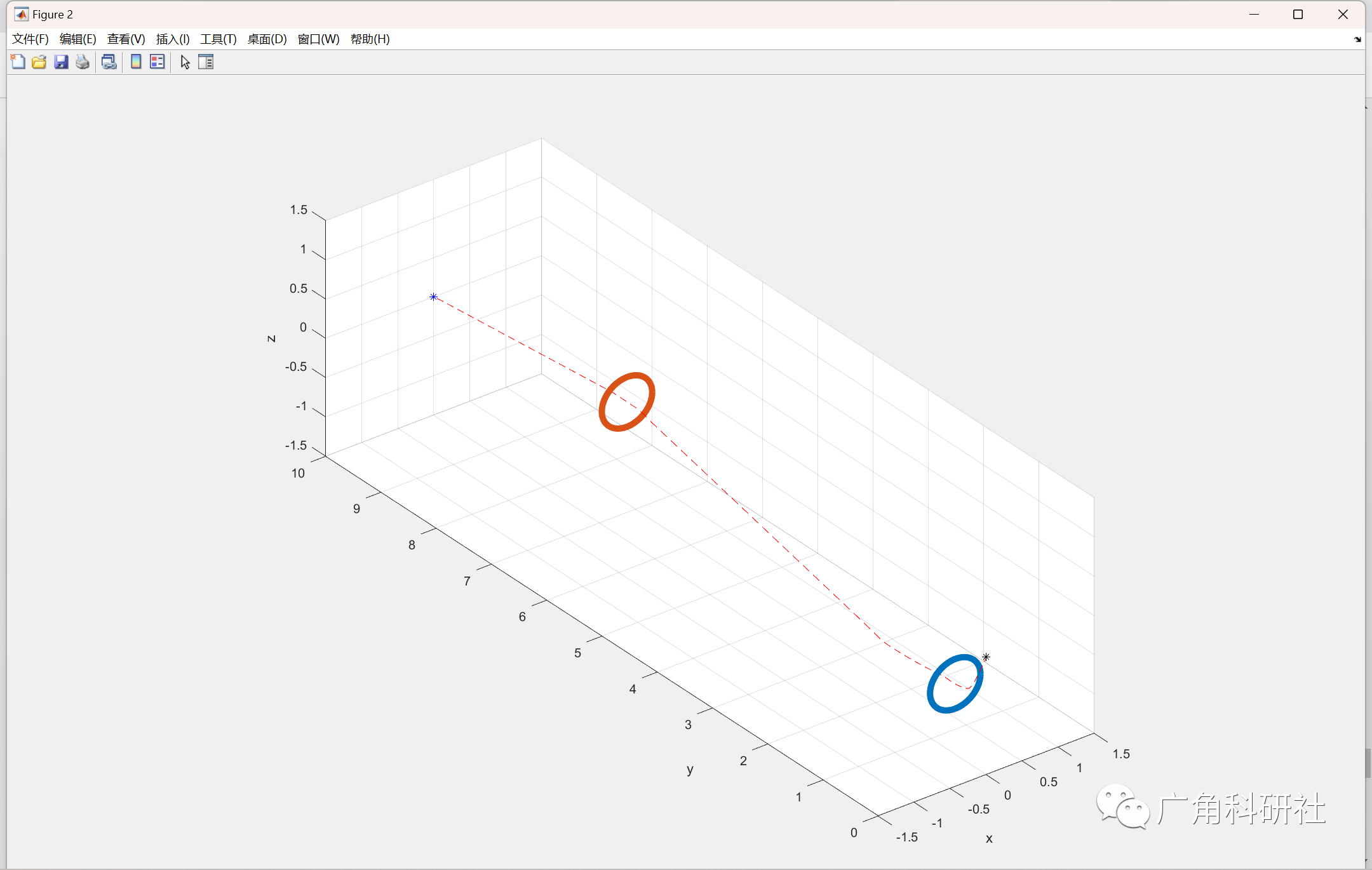
%% Animate results
figure('units','normalized','outerposition',[0 0 1 1])
plot3(ring1(1)+1*newPnts(1,:), ring1(3)+1*newPnts(2,:), ring1(5)+1*newPnts(3,:), 'LineWidth',5)
hold on
plot3(ring2(1)+1*newPnts(1,:), ring2(3)+1*newPnts(2,:), ring2(5)+1*newPnts(3,:), 'LineWidth',5)
plot3(goal(1), goal(3), goal(5), 'b*')
plot3(x0(1), x0(3), x0(5), 'k*')
xlabel('x'); ylabel('y'); zlabel('z');
xlim([-1.5 1.5]); ylim([0 10]); zlim([-1.5 1.5])
pbaspect([3 10 3])
grid on
tic
for i = 1:simT/Ts
plot3(results.state(1:i, 1), results.state(1:i, 3), results.state(1:i, 5), 'r--');
p1 = plot3(results.state(i, 1), results.state(i, 3), results.state(i,5), 'r.');
pause(Ts/2)
% F(i) = getframe;
delete(p1)
end
🎉3 参考文献
[1]聂博文,马宏绪,王剑,王建文.微小型四旋翼飞行器的研究现状与关键技术[J].电光与控制,2007(06):113-117.
部分理论引用网络文献,若有侵权联系博主删除。


 1138
1138


 被折叠的 条评论
为什么被折叠?
被折叠的 条评论
为什么被折叠?
 到【灌水乐园】发言


