


 本文详细介绍了RaspberryPiPicoRP2xxx开发板的特性和功能,包括微控制器技术规格、可编程IO(PIO)、MicroPython安装、电路板控制、延迟与定时、定时器、GPIO、PWM、ADC、SPI/I2C通信、实时时钟、看门狗定时器、单线驱动器以及NeoPixel和APA106驱动器的使用。
系列文章目录
前言
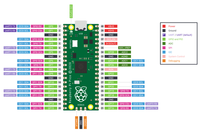
Raspberry Pi Pico 开发板(图片来源:Raspberry Pi 基金会)。
以下是 Raspberry Pi RP2xxx 板的快速参考资料。如果您是第一次使用该开发板,了解微控制器的概况可能会对您有所帮助:
一、关于 RP2xxx 端口的一般信息
rp2 端口支持由 Raspberry Pi 基金会的 RP2xxx 系列微控制器驱动的电路板,特别是采用 RP2040 的 Raspberry Pi Pico。
技术规格和 SoC 数据表
有关详细技术规格,请参阅数据表
RP2040 微控制器采用 40 纳米硅工艺制造,采用 7x7mm QFN-56 SMD 封装。主要特性包括
- 133 MHz 双 ARM Cortex-M0+ 内核(可超频至 400 MHz 以上)
- 264KB SRAM,分六个独立组
- 无内部闪存或 EEPROM 存储器(复位后,引导加载程序将固件从外部闪存或 USB 总线加载到内部 SRAM 中)
- QSPI 总线控制器,支持高达 16 MB 的外部闪存
- 片内可编程 LDO,用于产生内核电压
- 2 个片上 PLL,用于产生 USB 和内核时钟
- 30 个 GPIO 引脚,其中 4 个可选用作模拟输入
外设包括
- 2 个 UART
- 2 个 SPI 控制器
- 2 个 I2C 控制器
- 16 个 PWM 通道
- USB 1.1 控制器
- 8 个 PIO 状态机
二、可编程 IO
RP2040 硬件支持 I2C、SPI 和 UART 等标准通信协议。对于没有硬件支持或需要自定义 I/O 行为的协议,可编程输入输出 (PIO) 就能发挥作用。此外,一些 MicroPython 应用程序还使用了一种称为 "比特撞击 "的技术,即快速打开和关闭引脚以传输数据。这可能会使整个过程变得缓慢,因为处理器会专注于比特敲击,而不是执行其他逻辑。不过,PIO 允许在 CPU 执行主要工作时在后台进行位操作。
除了两个中央 Cortex-M0+ 处理内核,RP2040 还有两个 PIO 模块,每个模块有四个独立的状态机。这些状态机可以使用先进先出(FIFO)缓冲器与其他实体之间传输数据,从而使状态机和主处理器既能独立工作,又能同步数据。每个 FIFO 有四个字(每个字 32 位),可与 DMA 相连,以传输更大量的数据。
所有 PIO 指令都遵循一个共同的模式:
<instruction> .side(<side_set_value>) [<delay_value>]side-set .side(...)和 delay [...] 部分都是可选的,如果指定,则允许指令执行多个操作。这样可以保持 PIO 程序的小巧和高效。
有九条指令执行以下任务:
- jmp() 将控制权转移到代码的另一部分
- wait()暂停,直到特定操作发生
- in_() 将位从源(从头寄存器或引脚集)移至输入移位寄存器
- out()将比特从输出移位寄存器移位到目的地
- push() 向 RX FIFO 发送数据
- pull() 从 TX FIFO 接收数据
- mov()将数据从源移至目的位
- irq() 设置或清除 IRQ 标志
- set() 向目的地写入一个字面值
指令修改器有
- .side() 在指令开始时设置侧置引脚
- []在指令执行后延迟一定周期数
指令还有
- wrap_target()指定程序继续执行的位置
- wrap()指定程序的控制流从哪条指令开始包装
- label()设置与 jmp()指令一起使用的标签
- word() 发出一个 16 位原始值,作为程序中的一条指令
示例
以 pio_1hz.py 为例,简单了解如何使用 PIO 和状态机。以下代码可供参考。
# Example using PIO to blink an LED and raise an IRQ at 1Hz.

import time
from machine import Pin
import rp2


@rp2.asm_pio(set_init=rp2.PIO.OUT_LOW)
def blink_1hz():
    # Cycles: 1 + 1 + 6 + 32 * (30 + 1) = 1000
    irq(rel(0))
    set(pins, 1)
    set(x, 31)                  [5]
    label("delay_high")
    nop()                       [29]
    jmp(x_dec, "delay_high")

    # Cycles: 1 + 1 + 6 + 32 * (30 + 1) = 1000
    nop()
    set(pins, 0)
    set(x, 31)                  [5]
    label("delay_low")
    nop()                       [29]
    jmp(x_dec, "delay_low")


# Create the StateMachine with the blink_1hz program, outputting on Pin(25).
sm = rp2.StateMachine(0, blink_1hz, freq=2000, set_base=Pin(25))

# Set the IRQ handler to print the millisecond timestamp.
sm.irq(lambda p: print(time.ticks_ms()))

# Start the StateMachine.
sm.active(1)
这将创建一个 rp2.StateMachine 类的实例,该实例以 2000Hz 的频率运行 blink_1hz 程序,并连接到 25 引脚。blink_1hz 程序使用 PIO 以 1Hz 的频率闪烁连接到该引脚的 LED,并在 LED 亮起时引发 IRQ。然后,该 IRQ 调用 lambda 函数,该函数将打印出毫秒级的时间戳。
blink_1hz 程序是一个 PIO 汇编例程。它连接到单个引脚,该引脚被配置为输出,一开始为低电平。指令执行如下:
- irq(rel(0)) 引发与状态机相关的 IRQ。
- 通过 set(pins, 1) 指令打开 LED。
- 将值 31 放入寄存器 X,然后再延迟 5 个周期(由 [5] 指定)。
- nop() [29] 指令等待 30 个周期。
- 只要寄存器 X 不为零,jmp(x_dec, "delay_high")指令就会一直循环到 delay_high 标签处,并对 X 进行后递减。由于 X 的起始值为 31,这种跳转将发生 31 次,因此 nop() [29] 共运行 32 次(注意这 32 次循环中的每一次,jmp 都会占用一个指令周期)。
- 单个 nop() 与 IRQ 提升所用的周期相关,并确保 LED 开启和关闭所用的周期数相同。
- set(pins,0)将通过把引脚 25 设置为低电平来关闭 LED。
- 另外还将执行 32 个 nop() [29] 和 jmp(...) 循环。
- 由于没有指定 wrap_target() 和 wrap(),因此将使用它们的默认值,程序的执行将从底部绕到顶部。这种缠绕不会耗费任何执行周期。
整个例程正好占用状态机 2000 个周期。将状态机的频率设置为 2000Hz,LED 就会以 1Hz 的频率闪烁。
三、安装 MicroPython
请参阅教程的相应部分: 在 RP2xxx 上开始使用 MicroPython。其中还包括故障排除小节。
四、一般电路板控制
MicroPython REPL 通过 USB 串口访问。Tab-completion 在查找对象的方法时非常有用。粘贴模式 (ctrl-E) 用于将一大段 Python 代码粘贴到 REPL 中。
machine 模块:
import machine

machine.freq()          # get the current frequency of the CPU
machine.freq(240000000) # set the CPU frequency to 240 MHz
rp2 模块:
import rp2五、延迟和定时
使用 time 模块:
import time

time.sleep(1)           # sleep for 1 second
time.sleep_ms(500)      # sleep for 500 milliseconds
time.sleep_us(10)       # sleep for 10 microseconds
start = time.ticks_ms() # get millisecond counter
delta = time.ticks_diff(time.ticks_ms(), start) # compute time difference
六、定时器
RP2040 的系统定时器外设提供全局微秒时基,并为其产生中断。目前可使用软件定时器,数量不限(内存允许)。无需指定定时器 id(目前支持 id=-1),因为它会默认为该值。
请使用 machine.Timer 类:
from machine import Timer

tim = Timer(period=5000, mode=Timer.ONE_SHOT, callback=lambda t:print(1))
tim.init(period=2000, mode=Timer.PERIODIC, callback=lambda t:print(2))
七、引脚和 GPIO
使用 machine.Pin 类:
from machine import Pin

p0 = Pin(0, Pin.OUT)    # create output pin on GPIO0
p0.on()                 # set pin to "on" (high) level
p0.off()                # set pin to "off" (low) level
p0.value(1)             # set pin to on/high

p2 = Pin(2, Pin.IN)     # create input pin on GPIO2
print(p2.value())       # get value, 0 or 1

p4 = Pin(4, Pin.IN, Pin.PULL_UP) # enable internal pull-up resistor
p5 = Pin(5, Pin.OUT, value=1) # set pin high on creation
八、可编程 IO (PIO)
PIO 对于从头开始构建低级 IO 接口非常有用。有关汇编指令的详细解释,请参阅 rp2 模块。
使用 PIO 以 1Hz 闪烁 LED 的示例:
from machine import Pin
import rp2

@rp2.asm_pio(set_init=rp2.PIO.OUT_LOW)
def blink_1hz():
    # Cycles: 1 + 7 + 32 * (30 + 1) = 1000
    set(pins, 1)
    set(x, 31)                  [6]
    label("delay_high")
    nop()                       [29]
    jmp(x_dec, "delay_high")

    # Cycles: 1 + 7 + 32 * (30 + 1) = 1000
    set(pins, 0)
    set(x, 31)                  [6]
    label("delay_low")
    nop()                       [29]
    jmp(x_dec, "delay_low")

# Create and start a StateMachine with blink_1hz, outputting on Pin(25)
sm = rp2.StateMachine(0, blink_1hz, freq=2000, set_base=Pin(25))
sm.active(1)
九、UART(串行总线)
有两个 UART,即 UART0 和 UART1。UART0 可映射到 GPIO 0/1、12/13 和 16/17,UART1 可映射到 GPIO 4/5 和 8/9。
参见 machine.UART。
from machine import UART, Pin
uart1 = UART(1, baudrate=9600, tx=Pin(4), rx=Pin(5))
uart1.write('hello')  # write 5 bytes
uart1.read(5)         # read up to 5 bytes
注意事项
UART 上的 REPL 默认为禁用。有关如何启用 UART 上的 REPL 的详细信息,请参阅 RP2xxx 上的 MicroPython 入门。
十、PWM(脉宽调制)
有 8 个独立的 PWM 发生器(称为片),每个片有两个通道,总共有 16 个 PWM 通道,时钟频率从 8Hz 到 62.5Mhz,machine.freq() 为 125Mhz。一个片的两个通道以相同的频率运行,但可以有不同的占空比。这两个通道通常分配给相邻的偶数/奇数 GPIO 引脚对。因此 GPIO0 和 GPIO1 位于片 0,GPIO2 和 GPIO3 位于片 1,以此类推。某个通道可以分配给不同的 GPIO 引脚(参见引脚分配)。例如,片 0 的通道 A 可以分配给 GPIO0 和 GPIO16。
使用 machine.PWM 类:
from machine import Pin, PWM

# create PWM object from a pin and set the frequency of slice 0
# and duty cycle for channel A
pwm0 = PWM(Pin(0), freq=2000, duty_u16=32768)
pwm0.freq()             # get the current frequency of slice 0
pwm0.freq(1000)         # set/change the frequency of slice 0
pwm0.duty_u16()         # get the current duty cycle of channel A, range 0-65535
pwm0.duty_u16(200)      # set the duty cycle of channel A, range 0-65535
pwm0.duty_u16(0)        # stop the output at channel A
print(pwm0)             # show the properties of the PWM object.
pwm0.deinit()           # turn off PWM of slice 0, stopping channels A and B
十一、ADC(模数转换)
RP2040 共有五个 ADC 通道,其中四个是基于 12 位 SAR 的 ADC: GP26、GP27、GP28 和 GP29。ADC0、ADC1、ADC2 和 ADC3 的输入信号可分别连接到 GP26、GP27、GP28 和 GP29(在 Pico 板上,GP29 连接到 VSYS)。标准 ADC 范围为 0-3.3V。第五个通道与内置温度传感器相连,可用于测量温度。
使用 machine.ADC 类:
from machine import ADC, Pin
adc = ADC(Pin(26))     # create ADC object on ADC pin
adc.read_u16()         # read value, 0-65535 across voltage range 0.0v - 3.3v
十二、软件 SPI 总线
软件 SPI(使用位操作)适用于所有引脚,并可通过 machine.SoftSPI 类访问:
from machine import Pin, SoftSPI

# construct a SoftSPI bus on the given pins
# polarity is the idle state of SCK
# phase=0 means sample on the first edge of SCK, phase=1 means the second
spi = SoftSPI(baudrate=100_000, polarity=1, phase=0, sck=Pin(0), mosi=Pin(2), miso=Pin(4))

spi.init(baudrate=200000) # set the baudrate

spi.read(10)            # read 10 bytes on MISO
spi.read(10, 0xff)      # read 10 bytes while outputting 0xff on MOSI

buf = bytearray(50)     # create a buffer
spi.readinto(buf)       # read into the given buffer (reads 50 bytes in this case)
spi.readinto(buf, 0xff) # read into the given buffer and output 0xff on MOSI

spi.write(b'12345')     # write 5 bytes on MOSI

buf = bytearray(4)      # create a buffer
spi.write_readinto(b'1234', buf) # write to MOSI and read from MISO into the buffer
spi.write_readinto(buf, buf) # write buf to MOSI and read MISO back into buf
警告
目前,在初始化软件 SPI 时必须指定所有 sck、mosi 和 miso。
十三、硬件 SPI 总线
RP2040 有两个硬件 SPI 总线,可通过 machine.SPI 类访问,其方法与上述软件 SPI 相同:
from machine import Pin, SPI

spi = SPI(1, 10_000_000)  # Default assignment: sck=Pin(10), mosi=Pin(11), miso=Pin(8)
spi = SPI(1, 10_000_000, sck=Pin(14), mosi=Pin(15), miso=Pin(12))
spi = SPI(0, baudrate=80_000_000, polarity=0, phase=0, bits=8, sck=Pin(6), mosi=Pin(7), miso=Pin(4))
十四、软件 I2C 总线
软件 I2C(使用位敲击)适用于所有可输出引脚,并通过 machine.SoftI2C 类访问:
from machine import Pin, SoftI2C

i2c = SoftI2C(scl=Pin(5), sda=Pin(4), freq=100_000)

i2c.scan()              # scan for devices

i2c.readfrom(0x3a, 4)   # read 4 bytes from device with address 0x3a
i2c.writeto(0x3a, '12') # write '12' to device with address 0x3a

buf = bytearray(10)     # create a buffer with 10 bytes
i2c.writeto(0x3a, buf)  # write the given buffer to the peripheral
十五、硬件 I2C 总线
通过 machine.I2C 类访问驱动程序,其方法与上述软件 I2C 相同:
from machine import Pin, I2C

i2c = I2C(0)   # default assignment: scl=Pin(9), sda=Pin(8)
i2c = I2C(1, scl=Pin(3), sda=Pin(2), freq=400_000)
十六、I2S 总线
参见 machine.I2S。
from machine import I2S, Pin

i2s = I2S(0, sck=Pin(16), ws=Pin(17), sd=Pin(18), mode=I2S.TX, bits=16, format=I2S.STEREO, rate=44100, ibuf=40000) # create I2S object
i2s.write(buf)             # write buffer of audio samples to I2S device

i2s = I2S(1, sck=Pin(0), ws=Pin(1), sd=Pin(2), mode=I2S.RX, bits=16, format=I2S.MONO, rate=22050, ibuf=40000) # create I2S object
i2s.readinto(buf)          # fill buffer with audio samples from I2S device
ws 引脚编号必须比 sck 引脚编号大一个。
I2S 类目前是技术预览版。在预览期间,我们鼓励用户提供反馈意见。根据这些反馈,I2S 类的 API 和实现可能会有所改变。
支持 id=0 和 id=1 两种 I2S 总线。
十七、实时时钟(RTC)
参见 machine.RTC
from machine import RTC

rtc = RTC()
rtc.datetime((2017, 8, 23, 2, 12, 48, 0, 0)) # set a specific date and
                                             # time, eg. 2017/8/23 1:12:48
rtc.datetime() # get date and time
十八、WDT(看门狗定时器)
RP2040 有一个看门狗,它是一个倒计时器,可以在倒计时为零时重启芯片的某些部分。
请参阅 machine.WDT。
from machine import WDT

# enable the WDT with a timeout of 5s (1s is the minimum)
wdt = WDT(timeout=5000)
wdt.feed()
超时最大值为 8388 毫秒。
十九、单线驱动器 OneWire driver
单线驱动器由软件实现,可用于所有引脚:
from machine import Pin
import onewire

ow = onewire.OneWire(Pin(12)) # create a OneWire bus on GPIO12
ow.scan()               # return a list of devices on the bus
ow.reset()              # reset the bus
ow.readbyte()           # read a byte
ow.writebyte(0x12)      # write a byte on the bus
ow.write('123')         # write bytes on the bus
ow.select_rom(b'12345678') # select a specific device by its ROM code
DS18S20 和 DS18B20 设备有专门的驱动程序:
import time, ds18x20
ds = ds18x20.DS18X20(ow)
roms = ds.scan()
ds.convert_temp()
time.sleep_ms(750)
for rom in roms:
    print(ds.read_temp(rom))
确保在数据线上加一个 4.7k 的上拉电阻。请注意,每次对温度进行采样时,都必须调用 convert_temp() 方法。
二十、NeoPixel 和 APA106 驱动器
使用 neopixel 和 apa106 模块:
from machine import Pin
from neopixel import NeoPixel

pin = Pin(0, Pin.OUT)   # set GPIO0 to output to drive NeoPixels
np = NeoPixel(pin, 8)   # create NeoPixel driver on GPIO0 for 8 pixels
np[0] = (255, 255, 255) # set the first pixel to white
np.write()              # write data to all pixels
r, g, b = np[0]         # get first pixel colour
APA106 驱动程序扩展了 NeoPixel,但内部使用了不同的颜色顺序:
from apa106 import APA106
ap = APA106(pin, 8)
r, g, b = ap[0]
APA102 (DotStar) 使用不同的驱动器,因为它有一个额外的时钟引脚。


 510
510


 被折叠的 条评论
为什么被折叠?
被折叠的 条评论
为什么被折叠?
 到【灌水乐园】发言


