


上文拆解了SX1261/2的6种工作模式,本文将拆解MCU通过射频芯片SX1261/2物理帧如何进行数据包收发的。
一. 射频芯片功能模式以及与MCU之间的操作接口
1. 功能模块

2. 操作接口

在上述电路中,MCU通过SPI接口访问LoRa芯片内部的寄存器,也是通过SPI接口操作芯片内部的FIFO,用于收发数据包。
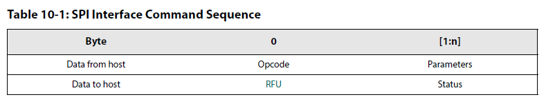
不同于那些把所有操作都直接基于“寄存器地址空间”访问的芯片,LoRa视频芯片暴露给MCU的是:基于“命令”的访问。有点类似所谓的AT命令的格式。
因此MCU是通过“命令”的方式配置、管理、控制LoRa芯片的工作方式。
同时MCU也是通过“命令”的方式,从LoRa内部data buffer中读取数据,向LoRa内部data buffer中写入数据。
SX1261/2通过GPIO busy管脚向MCU指示,当前是否正在执行某一个命令,命令的执行是否完成,以允许或禁止执行下一个命令。
MCU可以通过置位NSS复位管脚,强制SX1261/2终止正在执行的命令。
3.命令格式:
二. SX1261/2的内部数据缓冲区FIFO
1. 内部buffer的结构
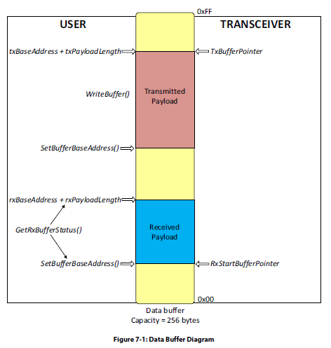
SX1261/2内部有256字节的内存buffer,用于MCU发送和接收数据,为接收和发送共享。用于发送和接收的buffer的大小,完全由MCU设置。
RxBaseAdress:用于保存MCU设置的接收buffer的起始地址,并通过setBufferBaseAddress命令设置。
RxPayloadLength:用于保存射频芯片接收到的实际的数据包的长度,并通过GetRxBufferStatus命令获取。
RxStartBufferPointer):当前接收buffer其实数据的位置。并通过GetRxBufferStatus命令获取。

TxBaseAddr:用于保存MCU设置的发送buffer的起始地址,并通过setBufferBaseAddress命令设置。
TxDataPointer:指向可写数据buffer的其实地址,初始值为TxBaseAddr,一旦写入数据,该指针就会自动增长。
2. 接收和发送buffer起始地址的设置

Tx base address和RxBase adress是有MCU设置的。
需要说明的是,总的内存大小256字节,也就是说接收和发送,同时共享的化 ,平均各自只有128字节。
3. 包的长度的设置:
发送和接收包的长度有SetPacketParams命令来设置。
备注:
由于不支持同时收发,因此如果发送和接收的数据包的净荷长度超过128字节,接收的buffer和发送的buffer就可能重叠,而不像上图展示的发送和接收地址是错开的。
三、LoRa物理层帧的结构
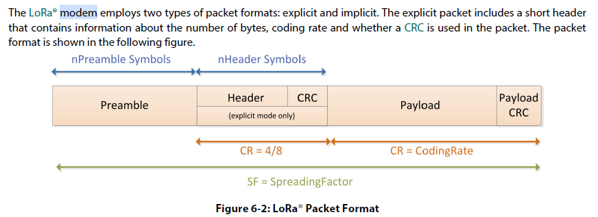
需要注意的是:在LoRa调制解调模式下,帧的前导和帧同信息,包括同步字,地址域是不需要设置的。
四.、FSK调制前的物理层帧结构
SX1261/2提供了两种FSK的帧结构:
一是固定长度的帧结构,帧的长度在接收和发送双方都已经实现约定好,因此,帧中可以不用包含长度域。
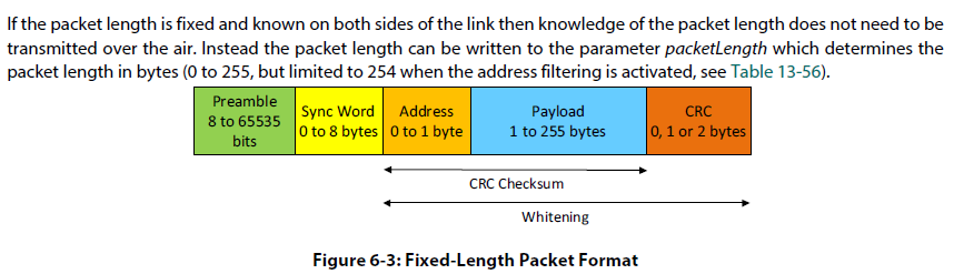
另一种就可变长度域,这样就需要把长度域添加的数据帧中。

五、数据帧的发送过程
0. power on and come into standby mode.
1.If not in STDBY_RC mode, then go to this mode with the command SetStandby(...):切换到standby 模式
2.Define the protocol (LoRa orFSK) with the command SetPacketType(...):设置调制解调器的类型
3.Define the RF frequency with the command SetRfFrequency(...):设置过载频频率的中心频点
4.Define the Power Amplifier configuration with the command SetPaConfig(...):设置功率放大器功率放大倍数
5.Define output power and ramping time with the command SetTxParams(...):设置功率放大的参数
6.Define where the data payload will be stored with the command SetBufferBaseAddress(...):设置发送Bufffer的起始地址
7.Send the payload to the data buffer with the command WriteBuffer(...):把需要发送payload数据写到buffer中。
注意:
写入buffer中存放的数据只包括payload净荷,不包括帧头信息:前导,同步字,长度和地址。发送时,这些信息存放在寄存器中,有自动添加到发送的物理帧中。无论是变长帧还是股东长度帧,长度域不在净荷中。
8.Define the modulation parameter according to the chosen protocol with the command SetModulationParams(...):设置调制器的参数
9.Define the frame format to be used with the command SetPacketParams(...):定义物理层帧的格式,主要是帧头信息,前导,同步字,长度和地址。数据净荷已经在第7步准备好了。
注意:这里的设置仅仅针对FSK模式,LoRa调制模式下,物理层的帧头信息是不需要配置的,属于LoRa私有协议部分。
10.Configure DIO and IRQ: use the command SetDioIrqParams(...) to select TxDone IRQ and map this IRQ to a DIO (DIO1, DIO2 or DIO3): 设置哪个IO哪些IO管脚用于发送中断。
11.Define Sync Word value: use the command WriteReg(...) to write the value of the register via direct register access:定义双方的物理层帧的同步字。
12.Set the circuit in transmitter mode to start transmission with the command SetTx(). Use the parameter to enable Timeout:启动发送
13.Wait for the IRQ TxDone or Timeout: once the packet has been sent the chip goes automatically to STDBY_RC mode:MCU等待发送的完成或超时。一旦发送数据完成,切换芯片的状态,进入standby模式。
14.Clear the IRQ TxDone flag:清除发送中断。
六、数据帧的接收过程
0. power on and come into standby mode:重启进入standby模式
1.If not in STDBY_RC mode, then set the circuit in this mode with the command SetStandby():进入standby模式
2.Define the protocol (LoRa® or FSK) with the command SetPacketType(...):设置调制解调器的类型
3.Define the RF frequency with the command SetRfFrequency(...):设置过载频频率的中心频点
4.Define where the data will be stored inside the data buffer in Rx with the command SetBufferBaseAddress(...):设置数据用于接收数据净荷的其实内存的地址。
5.Define the modulation parameter according to the chosen protocol with the command SetModulationParams(...):定义解调器的参数。
6.Define the frame format to be used with the command SetPacketParams(...):定义允许接收的合法的数据帧的格式,这也要是帧头信息:,前导,同步字,长度和地址。
这里还包括广播地址和自身的地址信息。地址信息用于指明,数据帧是否属于自己,如果地址与自动的地址不一致,需要丢掉该物理层的帧。
注意:这里的设置仅仅针对FSK模式,LoRa调制模式下,物理层的帧头信息是不需要配置的,属于LoRa私有协议部分。
7.Configure DIO and irq: use the command SetDioIrqParams(...) to select the IRQ RxDone and map this IRQ to a DIO (DIO1 or DIO2 or DIO3), set IRQ Timeout as well.:定义用于接收终端的IO管脚信息。
8.Define Sync Word value: use the command WriteReg(...) to write the value of the register via direct register access:定义物理层帧的同步字。
9.Set the circuit in reception mode: use the command SetRx(). Set the parameter to enable timeout or continuous mode:进入接收模式,启动数据的接收。
10.Wait for IRQ RxDone or Timeout: the chip will stay in Rx and look for a new packet if the continuous mode is selected
otherwise it will goes to STDBY_RC mode.
等待有效数据的接收,
如果不是连续接收模式,自动关闭接收,进入standby模式,
如果是 连续接收模式,允许呆在Rx模式,继续接收数据包,这种模式就需要Mux一边读数据,射频芯片一边收数据。
11.In case of the IRQ RxDone, check the status to ensure CRC is correct: use the command GetIrqStatus():
Note:
The IRQ RxDone means that a packet has been received but the CRC could be wrong: the user must check the CRC before
validating the packet.
如果RxDone中断,还需要检查数据包的CRC是否正确,MCU以决定,是否需要接纳该数据包 。
12.Clear IRQ flag RxDone or Timeout: use the command ClearIrqStatus(). In case of a valid packet (CRC OK), get the packet length and address of the first byte of the received payload by using the command GetRxBufferStatus(...):清除接收中断,获取接收到的数据包的长度。
13.In case of a valid packet (CRC OK), start reading the packet:如果CRC OK, 则从Buffer中读取数据包。


 2万+
2万+


 被折叠的 条评论
为什么被折叠?
被折叠的 条评论
为什么被折叠?
 到【灌水乐园】发言


