


2023.7.23
这里先简单写下我的操作步骤,因为网上已经有很多关于手眼标定的原理,这里我就不多赘述,后续有时间会进行详细介绍。
下面的操作步骤需要你掌握eye_to_hand手眼标定的知识,话不多说,先给出标定操作步骤,这些都是个人见解,仅供参考,不对的地方还请各位在评论区指出,我们一起进步!
(由于最近没时间,不去介绍代码如何使用了,代码有点乱对小白并不友好,不懂的可以在评论区留言,我再进行修改解释)
一、获取三维坐标
这里我使用的是深度相机D435i,具体相关代码有空再补上。标定的代码是参考B站up手眼标定视频的方法,但他所使用的是UR5机械臂,与delta差别很大,我能力有限,没法直接使用,有大佬能将其直接用在delta机械臂上还请教教我!!!
我对他的代码进行了修改
主代码
#!/usr/bin/env python

import numpy as np
import time
import cv2
from real.realsenseD415 import Camera
from real.delta_chuanKo import Moving


# delta的运动范围
# workspace_limits = np.asarray([[0, 100], [-100, 100], [-400, -300]])
workspace_limits = np.asarray([[-0.05, 0.05], [-0.05, 0.05], [-0.4, -0.3]])
calib_grid_step = 0.05

# 棋盘格中心点相对于末端执行器的距离
# checkerboard_offset_from_tool = [0,-0.13,0.02]  # change me!
checkerboard_offset_from_tool = [0.13, -0.065, 0]

# Construct 3D calibration grid across workspace
# 这一部分就是生成机械臂移动的坐标
print(1 + (workspace_limits[0][1] - workspace_limits[0][0]) / calib_grid_step)
gridspace_x = np.linspace(workspace_limits[0][0], workspace_limits[0][1],
                          int(1 + (workspace_limits[0][1] - workspace_limits[0][0]) / calib_grid_step))
gridspace_y = np.linspace(workspace_limits[1][0], workspace_limits[1][1],
                          int(1 + (workspace_limits[1][1] - workspace_limits[1][0]) / calib_grid_step))
gridspace_z = np.linspace(workspace_limits[2][0], workspace_limits[2][1],
                          int(1 + (workspace_limits[2][1] - workspace_limits[2][0]) / calib_grid_step))
calib_grid_x, calib_grid_y, calib_grid_z = np.meshgrid(gridspace_x, gridspace_y, gridspace_z)
num_calib_grid_pts = calib_grid_x.shape[0] * calib_grid_x.shape[1] * calib_grid_x.shape[2]  # 得到的是有多少组坐标

calib_grid_x.shape = (num_calib_grid_pts, 1)
calib_grid_y.shape = (num_calib_grid_pts, 1)
calib_grid_z.shape = (num_calib_grid_pts, 1)
calib_grid_pts = np.concatenate((calib_grid_x, calib_grid_y, calib_grid_z), axis=1)

measured_pts = []
observed_pts = []
observed_pix = []

# d435i RGB相机的内参
cam_intrinsics = np.array([605.839, 0, 316.720, 0, 605.772, 254.539, 0, 0, 1]).reshape(3, 3)

# Move robot to each calibration point in workspace
# 将机械臂移动到工作空间中的
print('Collecting data...')
for calib_pt_idx in range(num_calib_grid_pts):
    tool_position = calib_grid_pts[calib_pt_idx, :]
    tool_config = [tool_position[0], tool_position[1], tool_position[2]]
    tool_config1 = [tool_position[0], tool_position[1], tool_position[2]]
    print(f"tool position and orientation:{tool_config1}")
    # 传给delta机械臂坐标
    Moving(tool_config[0] * 1000, tool_position[1] * 1000, tool_position[2] * 1000)
    time.sleep(5)  # k

    # Find checkerboard center
    # 查找棋盘格中心点
    checkerboard_size = (5, 5)
    refine_criteria = (cv2.TERM_CRITERIA_EPS + cv2.TERM_CRITERIA_MAX_ITER, 30, 0.001)
    # 获取机器人的相机数据,将颜色图像和深度图像分别赋值给 camera_color_img 和 camera_depth_img
    # 这里其实就是获取d435i的相机的颜色图和深度图像,只不过这里进行了集成
    camera_color_img, camera_depth_img, aligned_depth_frame,depth_intrin= Camera().get_data()
    bgr_color_data = cv2.cvtColor(camera_color_img, cv2.COLOR_RGB2BGR)  # 将相机颜色图像从 RGB 格式转换为 BGR 格式
    gray_data = cv2.cvtColor(bgr_color_data, cv2.COLOR_RGB2GRAY)  # BGR 格式转换为灰度图像
    # 寻找角点,找到角点,返回 checkerboard_found 为 true; corners为像素空间的角点
    # 第一个参数Image,传入拍摄的棋盘图Mat图像,必须是8位的灰度或者彩色图像;
    # 第二个参数patternSize,每个棋盘图上内角点的行列数,一般情况下,行列数不要相同,便于后续标定程序识别标定板的方向;
    # 第三个参数corners,用于存储检测到的内角点图像坐标位置,一般是数组形式;
    # 第四个参数flage:用于定义棋盘图上内角点查找的不同处理方式,有默认值。
    checkerboard_found, corners = cv2.findChessboardCorners(gray_data, checkerboard_size, None,
                                                            cv2.CALIB_CB_ADAPTIVE_THRESH)
    print(checkerboard_found)
    if checkerboard_found:
        # 角点进行亚像素级别的精确化优化,以提高角点的准确性
        corners_refined = cv2.cornerSubPix(gray_data, corners, (5, 5), (-1, -1), refine_criteria)

        # Get observed checkerboard center 3D point in camera space
        # 因为棋盘格是5*5,所以中间的格子是第12个索引,说白了就是为了获得棋盘格的中心点像素坐标
        checkerboard_pix = np.round(corners_refined[12, 0, :]).astype(int)
        checkerboard_z = camera_depth_img[checkerboard_pix[1]][checkerboard_pix[0]]
        # 下面就是用的像素坐标转换为相机坐标公式求出的XY,robot.cam_intrinsics也就是d435i的内参
        checkerboard_x = np.multiply(checkerboard_pix[0] - cam_intrinsics[0][2], checkerboard_z / cam_intrinsics[0][0])
        checkerboard_y = np.multiply(checkerboard_pix[1] - cam_intrinsics[1][2], checkerboard_z / cam_intrinsics[1][1])
        if checkerboard_z == 0:
            continue

        # Save calibration point and observed checkerboard center
        # 像素中心点的三维坐标
        observed_pts.append([checkerboard_x, checkerboard_y, checkerboard_z])
        # tool_position[2] += checkerboard_offset_from_tool
        # 得到机械臂的坐标
        tool_position = tool_position + checkerboard_offset_from_tool

        measured_pts.append(tool_position)
        observed_pix.append(checkerboard_pix)

        # Draw and display the corners
        # vis = cv2.drawChessboardCorners(robot.camera.color_data, checkerboard_size, corners_refined, checkerboard_found)
        # 第一个参数image,8位灰度或者彩色图像;
        # 第二个参数patternSize,每张标定棋盘上内角点的行列数;
        # 第三个参数corners,初始的角点坐标向量,同时作为亚像素坐标位置的输出,所以需要是浮点型数据;
        # 第四个参数patternWasFound,标志位,用来指示定义的棋盘内角点是否被完整的探测到,true表示别完整的探测到,
        # 函数会用直线依次连接所有的内角点,作为一个整体,false表示有未被探测到的内角点,这时候函数会以(红色)圆圈标记处检测到的内角点;
        vis = cv2.drawChessboardCorners(bgr_color_data, (1, 1), corners_refined[12, :, :], checkerboard_found)
        cv2.imwrite('%06d.png' % len(measured_pts), vis)
        image_RGB = np.hstack((vis, camera_color_img))
        # cv2.imshow('Calibration',vis)
        cv2.imshow('Calibration', image_RGB)
        cv2.waitKey(1000)
    else:
        print('------ 没找到角点 -------')

np.savetxt('measured_pts.txt', measured_pts, delimiter=' ')
np.savetxt('observed_pts.txt', observed_pts, delimiter=' ')
相机D435i代码
import time

import numpy as np
import pyrealsense2 as rs
import cv2

class Camera(object):

    def __init__(self,width=640,height=480,fps=30):
        self.im_height = height
        self.im_width = width
        self.fps = fps
        self.intrinsics = None
        self.scale = None
        self.pipeline = None
        self.connect()
        # color_img, depth_img = self.get_data()
        #print(color_img, depth_img)


    def connect(self):
        # Configure depth and color streams
        self.pipeline = rs.pipeline()
        config = rs.config()
        config.enable_stream(rs.stream.depth, self.im_width, self.im_height, rs.format.z16, self.fps)
        config.enable_stream(rs.stream.color, self.im_width, self.im_height, rs.format.bgr8, self.fps)
        # config.enable_stream(rs.stream.depth, 1280, 720, rs.format.z16, 6)  # 配置depth流
        # config.enable_stream(rs.stream.color, 1280, 720, rs.format.bgr8, 15)  # 配置color流

        # Start streaming
        cfg = self.pipeline.start(config)
        self.align = rs.align(rs.stream.color)

        # Determine intrinsics
        rgb_profile = cfg.get_stream(rs.stream.color)
        self.intrinsics = self.get_intrinsics(rgb_profile)
        # Determine depth scale
        self.scale = cfg.get_device().first_depth_sensor().get_depth_scale()
        print("camera depth scale:",self.scale)
        print("D415 have connected ...")
    def get_data(self):
        # Wait for a coherent pair of frames: depth and color
        time.sleep(1)
        frames = self.pipeline.wait_for_frames()

        # align
        # align = rs.align(align_to=rs.stream.color)
        aligned_frames = self.align.process(frames)
        aligned_depth_frame = aligned_frames.get_depth_frame()
        color_frame = aligned_frames.get_color_frame()
        # no align
        # depth_frame = frames.get_depth_frame()
        # color_frame = frames.get_color_frame()

        # Convert images to numpy arrays
        depth_image = np.asanyarray(aligned_depth_frame.get_data(),dtype=np.float32)
        # depth_image = np.asanyarray(aligned_depth_frame.get_data())
        # depth_image *= self.scale

        # 不注释掉在标定时会报错
        # depth_image = np.expand_dims(depth_image, axis=2) # 在 depth_image 数组中在第2个维度(axis=2,从0开始计数)上增加一个维度
        color_image = np.asanyarray(color_frame.get_data())
        depth_intrin = aligned_depth_frame.profile.as_video_stream_profile().intrinsics
        # 将深度图转化为伪彩色图方便观看, alpha=0.008可进行修改
        # depth_colormap = cv2.applyColorMap \
        #     (cv2.convertScaleAbs(depth_image, alpha=0.008)
        #      , cv2.COLORMAP_JET)
        return color_image, depth_image, aligned_depth_frame,depth_intrin  # 运行calibrate时,去掉最后两个

    def plot_image(self):
        color_image,depth_image = self.get_data()
        # Apply colormap on depth image (image must be converted to 8-bit per pixel first)
        depth_colormap = cv2.applyColorMap(cv2.convertScaleAbs(depth_image, alpha=0.03), cv2.COLORMAP_JET)

        depth_colormap_dim = depth_colormap.shape
        color_colormap_dim = color_image.shape

        # If depth and color resolutions are different, resize color image to match depth image for display
        if depth_colormap_dim != color_colormap_dim:
            resized_color_image = cv2.resize(color_image, dsize=(depth_colormap_dim[1], depth_colormap_dim[0]),
                                             interpolation=cv2.INTER_AREA)
            images = np.hstack((resized_color_image, depth_colormap))
        else:
            images = np.hstack((color_image, depth_colormap))
        # Show images
        cv2.namedWindow('RealSense', cv2.WINDOW_AUTOSIZE)
        cv2.imshow('RealSense', images)
        # cv2.imwrite('color_image.png', color_image)
        cv2.waitKey(5000)

    def get_intrinsics(self,rgb_profile):
        ''' 不同的分辨率下的内参也是不同的 '''
        raw_intrinsics = rgb_profile.as_video_stream_profile().get_intrinsics()
        # print("camera intrinsics:", raw_intrinsics)
        # camera intrinsics form is as follows.
        #[[fx,0,ppx],
        # [0,fy,ppy],
        # [0,0,1]]
        # intrinsics = np.array([615.284,0,309.623,0,614.557,247.967,0,0,1]).reshape(3,3) #640 480
        intrinsics = np.array([raw_intrinsics.fx, 0, raw_intrinsics.ppx, 0, raw_intrinsics.fy, raw_intrinsics.ppy, 0, 0, 1]).reshape(3, 3)

        return intrinsics
if __name__== '__main__':
    mycamera = Camera()
    # mycamera.get_data()
    mycamera.plot_image()
    print(mycamera.intrinsics)
放在同一目录两个py文件下,这个我不用多说了吧。
操作步骤
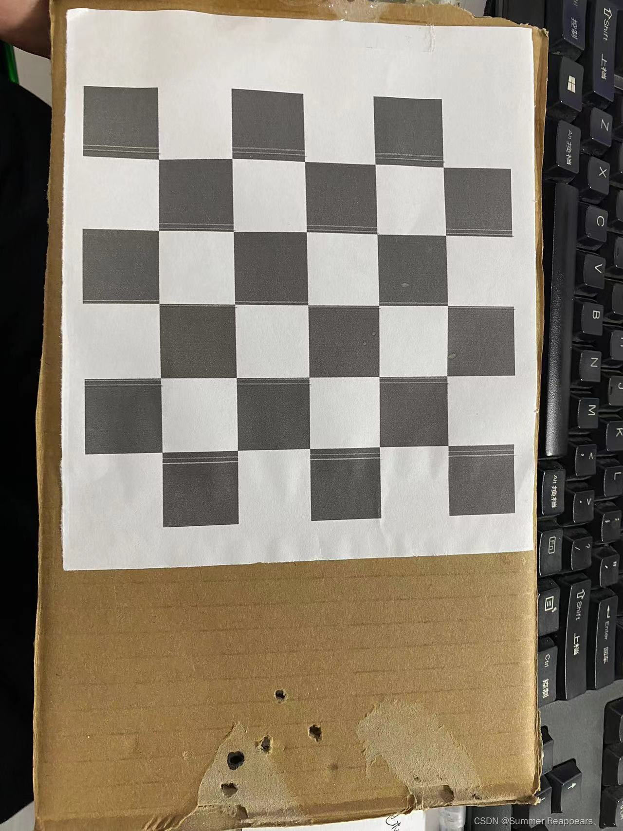
我将棋盘格的图片打印出来贴在了一个纸片上,可以看出很简陋,没关系,不影响试验使用。
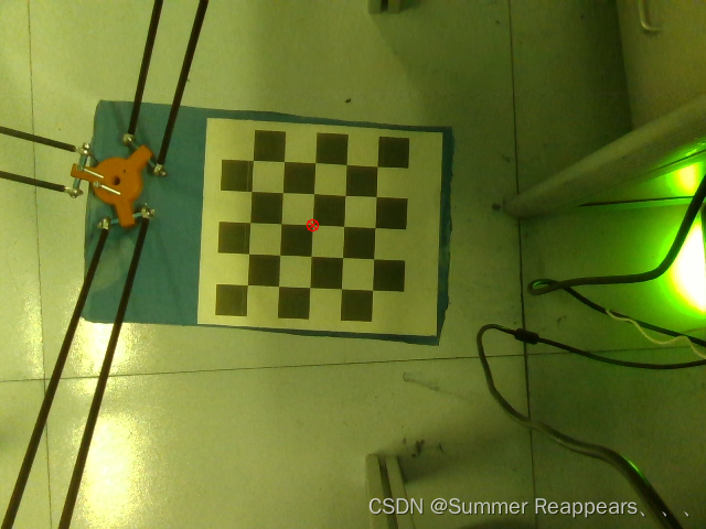
然后把制成的标定板放在delta机械臂末端,像图里那样,图里的红色原点是我在运行代码时自动生成保存的,也就是代码里的cv2.drawChessboardCorners。
二、Halcon计算旋转平移矩阵
使用B站UP的代码得出的矩阵我使用后给出的delta机械臂的XYZ坐标差的离谱,我实在不知道是啥原因,懂得大佬还请在评论区教教我啊!
所以我使用halcon中的vector_to_hom_mat3d算子来求解旋转平移矩阵,这个算子需要输入相机的xyz和机械臂的xyz,所以(一)中的代码主要就是为了获取这两个坐标xyz,坐标在下面图中的txt文件中。

然后你可以使用下边的代码输出xyz,复制到halcon中(如果不下halcon软件也是可以的,好像有python的包,可以去找一下)
import numpy as np

measured_pts = np.loadtxt(r'E:\DeltaX、GRCNN\real\measured_pts.txt', delimiter=' ')
measured_pts_x = list(measured_pts[:,0] * 1000)
print(measured_pts_x)
print(len(measured_pts_x))
measured_pts_y = list(measured_pts[:,1] * 1000)
print(measured_pts_y)
print(len(measured_pts_y))
measured_pts_z = list(measured_pts[:,2] * 1000)
print(measured_pts_z)

observed_pts = np.loadtxt(r'E:\DeltaX\GRCNN\real\observed_pts.txt', delimiter=' ')
observed_pts_x = list(observed_pts[:,0])
print(observed_pts_x)
print(len(observed_pts_x))
observed_pts_y = list(observed_pts[:,1])
print(observed_pts_y)
print(len(observed_pts_y))
observed_pts_z = list(observed_pts[:,2])
print(observed_pts_z)
print(len(observed_pts_z)) 

三、旋转矩阵使用
需要你点击图像一点,会给出机械臂的坐标,还是比较准确的
target_position
#!/usr/bin/env python

import matplotlib.pyplot as plt
import numpy as np
import time
import cv2
from realsenseD415 import Camera
import pyrealsense2 as rs
from UR_Robot import UR_Robot


# User options (change me)
# --------------- Setup options ---------------
# tcp_host_ip = '192.168.50.100' # IP and port to robot arm as TCP client (UR5)
# tcp_port = 30003
# tool_orientation = [-np.pi,0,0]
# ---------------------------------------------

# # Move robot to home pose
# robot = UR_Robot(tcp_host_ip,tcp_port)
# # robot.move_j([-np.pi, -np.pi/2, np.pi/2, 0, np.pi/2, np.pi])
# grasp_home = [0.4, 0, 0.4, -np.pi, 0, 0]  # you can change me
# robot.move_j_p(grasp_home)
# robot.open_gripper()
#
# # Slow down robot
# robot.joint_acc = 1.4
# robot.joint_vel = 1.05

# Callback function for clicking on OpenCV window
click_point_pix = ()
camera_color_img, camera_depth_img,aligned_depth_frame, depth_intrin = Camera().get_data()
cam_intrinsics = np.array([605.839, 0, 316.720, 0, 605.772, 254.539, 0, 0, 1]).reshape(3, 3)
cam_depth_scale = -3.906250000008885254e-04
cam_pose = np.loadtxt(r'E:\DeltaX\GRCNN\real\camera_pose.txt', delimiter=' ')


def mouseclick_callback(event, x, y, flags, param):
    if event == cv2.EVENT_LBUTTONDOWN:
        global camera, robot, click_point_pix
        click_point_pix = (x,y)

        dis = aligned_depth_frame.get_distance(x,y)
        print('深度距离为:',dis)
        camera_xyz = rs.rs2_deproject_pixel_to_point(depth_intrin, (x,y), dis)
        camera_xyz = list(camera_xyz)
        print('得到的三维坐标',camera_xyz)
        camera_xyz = np.array(camera_xyz) * 1000
        print('第二次得到的三维坐标',camera_xyz)

        camera_xyz.shape = (3,1)


        # Get click point in camera coordinates
        # click_z = camera_depth_img[y][x] * cam_depth_scale
        # click_x = np.multiply(x-cam_intrinsics[0][2],click_z/cam_intrinsics[0][0])
        # click_y = np.multiply(y-cam_intrinsics[1][2],click_z/cam_intrinsics[1][1])
        # if click_z == 0:
        #     return
        # click_point = np.asarray([click_x,click_y,click_z])
        # click_point.shape = (3,1)

        # Convert camera to robot coordinates
        # camera2robot = np.linalg.inv(robot.cam_pose)
        # camera2robot = cam_pose
        camera2robot = np.array([0.965468, -0.260343, -0.00966817, 200.678, -0.260111, -0.965363, 0.0203872, -121.872, -0.014641, -0.0171684, -0.999745, 100.716, 0, 0, 0, 1]).reshape(4,4)
        print(camera2robot)
        target_position = np.dot(camera2robot[0:3,0:3],camera_xyz) + camera2robot[0:3,3:]

        target_position = target_position[0:3,0]
        print(target_position)
        print(target_position.shape)
        # destination=np.append(target_position,tool_orientation)
        # robot.plane_grasp([target_position[0],target_position[1],target_position[2]])


# Show color and depth frames
cv2.namedWindow('color')
cv2.setMouseCallback('color', mouseclick_callback)
cv2.namedWindow('depth')

while True:
    camera_color_img, camera_depth_img,aligned_depth_frame, depth_intrin = Camera().get_data()
    camera_depth_img = camera_depth_img * 50
    bgr_data = cv2.cvtColor(camera_color_img, cv2.COLOR_RGB2BGR)
    if len(click_point_pix) != 0:
        bgr_data = cv2.circle(bgr_data, click_point_pix, 7, (0,0,255), 2)
    cv2.imshow('color', bgr_data)
    cv2.imshow('depth', camera_depth_img)

    if cv2.waitKey(1) == ord('c'):
        break

cv2.destroyAllWindows()


 879
879


 被折叠的 条评论
为什么被折叠?
被折叠的 条评论
为什么被折叠?
 到【灌水乐园】发言


