


测试平台Vivado 2017.2
在Vivado的Block设计里,全IP化逐渐形成了一种新型的设计方案,受Vivado内的IP可配置的GUI界面影响,使用IP要比RTL代码更有良好的用户体验;然而,在Block设计里,并不是只有IP这一种可添加并可配置,RTL也可实现上述功能,只需要在Block内右键Add Module..,会弹出下面界面:
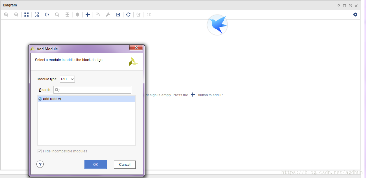
选择我之前写的模块add,点击ok,
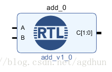
这样就添加了一个add的RTL Module到Block Design内了。默认Vivado左边是输入端口,右边是输出端口。
上面是一个很简单的操作,接下来进入正题,讲解如何利用IP Integrator HDL语言使我们的RTL Module在Block内更像一个IP,IP Integrator HDL语言支持Verilog、VHDL,这里只用Verilog进行演示。
先看一下Xilinx提供的IP Integrator HDL的Language Templates:
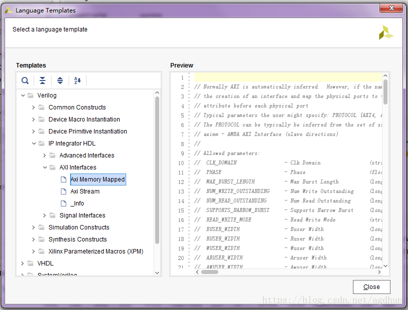
分析一下结构,得出以下几点结论:
1.每个端口定义都是以(*起始,并以*)结束,并写在端口定义之前;
2.每个端口定义结构满足 X_INTERFACE_INFO = "{存在的接口类型} {接口的名字} 接口内的端口(必须与接口类型定义的端口一致)"
3.除了端口定义,还有Parameter定义,以X_INTERFACE_PARAMETER = "开始,内部采用键值对,即Param = value型结构;
下面是vivado内的原话:
//
// Verilog attributes are used to declare signal interfaces and set parameters on them.
// Due to the language, the attributes need to be placed before a port which is part of the interface.
// When adding one or more parameters for an interface, a single attribute with multiple
// key value pairs should be added to before of the ports that is mapped into the interface.
// Generally, the form of the attributes are:
// (* X_INTERFACE_INFO = "<interface vlnv> <interface_name> <logical_port_name>" *)
// (* X_INTERFACE_PARAMETER = "<parameter_name1> <parameter_value1>, <parameter_name2> <parameter_value2>" *)
// input <portname>;
接下来以一个AXI4_controller模块做例子演示一下。
首先按上述步骤添加一个AXI4_controller模块到Block内:
module axi4_controller_top #(
    parameter DATA_WIDTH = 'h100,
    parameter ADDR_WIDTH = 'h20,
    parameter LENGTH_WIDTH = 'h8,
    parameter ID_WIDTH = 'h2,
    parameter MASTER_ID = 'h1,
    parameter CLK_FREQ = 'hc8,
    parameter BASE_ADDR = 'h000000
)(
//
//Other Port
//
    input s_axil_aclk0,
    input s_axil_aresetn0,
 最低0.47元/天 解锁文章


 7936
7936

 被折叠的 条评论
为什么被折叠?
被折叠的 条评论
为什么被折叠?
 到【灌水乐园】发言


