


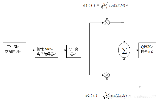
QPSK是英文Quadrature Phase Shift Keying的缩略语简称,意为正交相移键控,是一种数字调制方式。在19世纪80年代初期,人们选用恒定包络数字调制。这类数字调制技术的优点是已调信号具有相对窄的功率谱和对放大设备没有线性要求,不足之处是其频谱利用率低于线性调制技术。19世纪80年代中期以后,四相绝对移相键控(QPSK)技术以其抗干扰性能强、误码性能好、频谱利用率高等优点,广泛应用于数字微波通信系统、数字卫星通信系统、宽带接入、移动通信及有线电视系统之中。
clear;
%%%%%%%%%%%%%%%%%%%%%
%%% 初始化参数
%%%%%%%%%%%%%%%%%%%%%
T=1; % 基带信号宽度,也就是频率
fc=10/T; % 载波频率
ml=2; % 调制信号类型的一个标志位(选取2的原因见23行)
nb=100; % 传输的比特数
delta_T=T/200; % 采样间隔
fs=1/delta_T; % 采样频率
SNR=0; % 信噪比
t=0:delta_T:nb*T-delta_T; % 限定t的取值范围
N=length(t); % 采样数
%%%%%%%%%%%%%%%%%%%%%%%%%%%%%%%%%%%%%%%%%%%%%%%%%%%%%%%%%%%%%%%%%%%%%%%%%%%%%%%%%%
%%%%%%%%%%%%%%%%%%% 调制部分
%%%%%%%%%%%%%%%%%%%%%%%%%%%%%%%%%%%%%%%%%%%%%%%%%%%%%%%%%%%%%%%%%%%%%%%%%%%%%%%%%%
% 基带信号的产生
data=randn(1,nb)>0.5; % 调用一个随机函数(0 or 1),输出到一个1*100的矩阵
datanrz=data.*2-1; % 变成极性码
data1=zeros(1,nb/delta_T); % 创建一个1*nb/delta_T的零矩阵
for q=1:nb
data1((q-1)/delta_T+1:q/delta_T)=datanrz(q); % 将极性码变成对应的波形信号
end
% 将基带信号变换成对应波形信号
data0=zeros(1,nb/delta_T); % 创建一个1*nb/delta_T的零矩阵
for q=1:nb
data0((q-1)/delta_T+1:q/delta_T)=data(q); % 将极性码变成对应的波形信号
end
% 发射的信号
data2=abs(fft(data1));
% 串并转换,将奇偶位数据分开
idata=datanrz(1:ml:(nb-1)); % 将奇偶位分开,因此间隔m1为2
qdata=datanrz(2:ml:nb);
% QPSK信号的调制
ich=zeros(1,nb/delta_T/2); % 创建一个1*nb/delta_T/2的零矩阵,以便后面存放奇偶位数据
for i=1:nb/2
ich((i-1)/delta_T+1:i/delta_T)=idata(i);
end
for ii=1:N/2
a(ii)=sqrt(2/T)*cos(2*pi*fc*t(ii));
end
idata1=ich.*a; % 奇数位数据与余弦函数相乘,得到一路的调制信号
qch=zeros(1,nb/2/delta_T);
for j1=1:nb/2
qch((j1-1)/delta_T+1:j1/delta_T)=qdata(j1);
end
for jj=1:N/2
b(jj)=sqrt(2/T)*sin(2*pi*fc*t(jj));
end
qdata1=qch.*b; % 偶数位数据与余弦函数相乘,得到另一路的调制信号
s=idata1+qdata1; % 将奇偶位数据合并,s即为QPSK调制信号
ss=abs(fft(s)); % 快速傅里叶变换得到频谱
%%%%%%%%%%%%%%%%%%%%%%%%%%%%%%%%%%%%%%%%%%%%%%%%%%%%%%%%%%%%%%%%%%%%%%%%%%%%%%%%%
%%%%%%%%%%%%%%%%%%%%%%% 瑞利衰落信道和高斯信道
%%%%%%%%%%%%%%%%%%%%%%%%%%%%%%%%%%%%%%%%%%%%%%%%%%%%%%%%%%%%%%%%%%%%%%%%%%%%%%%%%
% 瑞利衰落信道
ray_ich=raylrnd(0.8,1,nb/2/delta_T);
ray_qch=raylrnd(0.8,1,nb/2/delta_T);
Ray_idata=idata1.*ray_ich;
Ray_qdata=qdata1.*ray_qch;
Ray_s=Ray_idata+Ray_qdata;
%%%%%%%%%%%%%%%%%%%%%%%%%%
% 高斯信道
s1=awgn(s,SNR); % 通过高斯信道之后的信号
s11=abs(fft(s1)); % 快速傅里叶变换得到频谱
s111=s1-s; % 高斯噪声曲线
%%%%%%%%%%%%%%%%%%%%%%%%%%
Awgn_s=awgn(Ray_s,SNR); % 通过高斯信道再通过瑞利衰落信道
%%%%%%%%%%%%%%%%%%%%%%%%%%%%%%%%%%%%%%%%%%%%%%%%%%%%%%%%%%%%%%%%%%%%%%%%%%%%%%%%%%
%%%%%%%%%%%%%%%%%%%%%%%%%%%%% QPSK 解调部分
%%%%%%%%%%%%%%%%%%%%%%%%%%%%%%%%%%%%%%%%%%%%%%%%%%%%%%%%%%%%%%%%%%%%%%%%%%%%%%%%%%
% 解调部分(高斯信道)
idata2=s1.*a; % 这里面其实隐藏了一个串并转换的过程
qdata2=s1.*b; % 对应的信号与正余弦信号相乘
idata3=zeros(1,nb/2); % 建立1*nb数组,以存放解调之后的信号
qdata3=zeros(1,nb/2);
% 抽样判决的过程,与0作比较,data>=0,则置1,否则置0
for n=1:nb/2
% A1(n)=sum(idata2((n-1)/delta_T+1:n/delta_T));
if sum(idata2((n-1)/delta_T+1:n/delta_T))>=0
idata3(n)=1;
else idata3(n)=0;
end
% A2(n)=sum(qdata2((n-1)/delta_T+1:n/delta_T));
if sum(qdata2((n-1)/delta_T+1:n/delta_T))>=0
qdata3(n)=1;
else qdata3(n)=0;
end
end
% 为了显示星座图,将信号进行处理
idata4=zeros(1,nb/2);
qdata4=zeros(1,nb/2);
for n=1:nb/2
Awgn_ichsum(n)=sum(idata2((n-1)/delta_T+1:n/delta_T))*delta_T;
if Awgn_ichsum(n)>=0
idata4(n)=1;
else idata4(n)=0;
end
Awgn_qchsum(n)=sum(qdata2((n-1)/delta_T+1:n/delta_T))*delta_T;
if Awgn_qchsum(n)>=0
qdata4(n)=1;
else qdata4(n)=0;
end
end
% 将判决之后的数据存放进数组
demodata=zeros(1,nb);
demodata(1:ml:(nb-1))=idata3; % 存放奇数位
demodata(2:ml:nb)=qdata3; % 存放偶数位
%为了显示,将它变成波形信号(即传输一个1代表单位宽度的高电平)
demodata1=zeros(1,nb/delta_T); % 创建一个1*nb/delta_T的零矩阵
for q=1:nb
demodata1((q-1)/delta_T+1:q/delta_T)=demodata(q); % 将极性码变成对应的波形信号
end
% 累计误码数
% abs(demodata-data)求接收端和发射端
% 数据差的绝对值,累计之后就是误码个数
Awgn_num_BER=sum(abs(demodata-data))
%%%%%%%%%%%%%%%%%%%
% 解调部分(瑞利+高斯)
Ray_idata2=Ray_s.*a; % 这里面其实隐藏了一个串并转换的过程
Ray_qdata2=Ray_s.*b; % 对应的信号与正余弦信号相乘
% Ray_idata3=zeros(1,nb/2); % 建立1*nb数组,以存放解调之后的信号
% Ray_qdata3=zeros(1,nb/2);
% 抽样判决的过程,与0作比较,data>=0,则置1,否则置0
% for n=1:nb/2
% if Ray_sum(Ray_idata2((n-1)/delta_T+1:n/delta_T))>=0
% Ray_idata3(n)=1;
% else Ray_idata3(n)=0;
% end
% if Ray_sum(Ray_qdata2((n-1)/delta_T+1:n/delta_T))>=0
% Ray_qdata3(n)=1;
% else Ray_qdata3(n)=0;
% end
% end
% 为了显示星座图,将信号进行处理
Ray_idata4=zeros(1,nb/2);
Ray_qdata4=zeros(1,nb/2);
for n=1:nb/2
Ray_ichsum(n)=sum(idata2((n-1)/delta_T+1:n/delta_T))*delta_T;
if Ray_ichsum(n)>=0
Ray_idata4(n)=1;
else Ray_idata4(n)=0;
end
Ray_qchsum(n)=sum(qdata2((n-1)/delta_T+1:n/delta_T))*delta_T;
if Ray_qchsum(n)>=0
Ray_qdata4(n)=1;
else Ray_qdata4(n)=0;
end
end
% 将判决之后的数据存放进数组
Ray_demodata=zeros(1,nb);
Ray_demodata(1:ml:(nb-1))=Ray_idata4; % 存放奇数位
Ray_demodata(2:ml:nb)=Ray_qdata4; % 存放偶数位
%为了显示,将它变成波形信号(即传输一个1代表单位宽度的高电平)
Ray_demodata1=zeros(1,nb/delta_T); % 创建一个1*nb/delta_T的零矩阵
for q=1:nb
Ray_demodata1((q-1)/delta_T+1:q/delta_T)=Ray_demodata(q); % 将极性码变成对应的波形信号
end
% 累计误码数
% abs(demodata-data)求接收端和发射端
% 数据差的绝对值,累计之后就是误码个数
Ray_num_BER=sum(abs(Ray_demodata-data))
%%%%%%%%%%%%%%%%%%%%%%%%%%%%%%%%%%%%%%%%%%%%%%%%%%
%% 误码率计算
%% 调用了cm_sm32();和cm_sm33()函数
%%声明: 函数声明在另外俩个M文件中
%%作用: cm_sm32()用于瑞利信道误码率的计算
%% cm_sm33()用于高斯信道误码率的计算
%% ecoh on/off 作用在于决定是否显示指令内容
%%%%%%%%%%%%%%%%%%%%%%%%%%%%%%%%%%%%%%%%%%%%%%%%%%
SNRindB1=0:1:6;
SNRindB2=0:0.1:6;
% 瑞利衰落信道
for i=1:length(SNRindB1),
[pb,ps]=cm_sm32(SNRindB1(i)); % 比特误码率
smld_bit_ray_err_prb(i)=pb;
smld_symbol_ray_err_prb(i)=ps;
disp([ps,pb]);
echo off;
end;
% 高斯信道
echo on;
for i=1:length(SNRindB1),
[pb1,ps1]=cm_sm33(SNRindB1(i));
smld_bit_awgn_err_prb(i)=pb1;
smld_symbol_awgn_err_prb(i)=ps1;
disp([ps1,pb1]);
echo off;
end;
% 理论曲线
echo on;
for i=1:length(SNRindB2),
SNR=exp(SNRindB2(i)*log(10)/10); % 信噪比
theo_err_awgn_prb(i)=0.5*erfc(sqrt(SNR)); % 高斯噪声理论误码率
theo_err_ray_prb(i)=0.5*(1-1/sqrt(1+1/SNR)); % 瑞利衰落信道理论误码率
echo off;
end;
%%%%%%%%%%%%%%%%%%%%%%%%%%%%%%%%%%%%%%%%%%%%%
h = spectrum.welch; % 类似于C语言的宏定义,方便以下的调用
%%%%%%%%%%%%%%%%%%%%%%%%%%%%%%%%%%%%%%%%%%%%%%%%%%%%%%%%%%%%%%%%%%%%%%%%%%%%%%%%%%%
%%%%%%%%%%%%%%%% 输出显示部分
%%%%%%%%%%%%%%%%%%%%%%%%%%%%%%%%%%%%%%%%%%%%%%%%%%%%%%%%%%%%%%%%%%%%%%%%%%%%%%%%%%%
% 第一部分(理想)
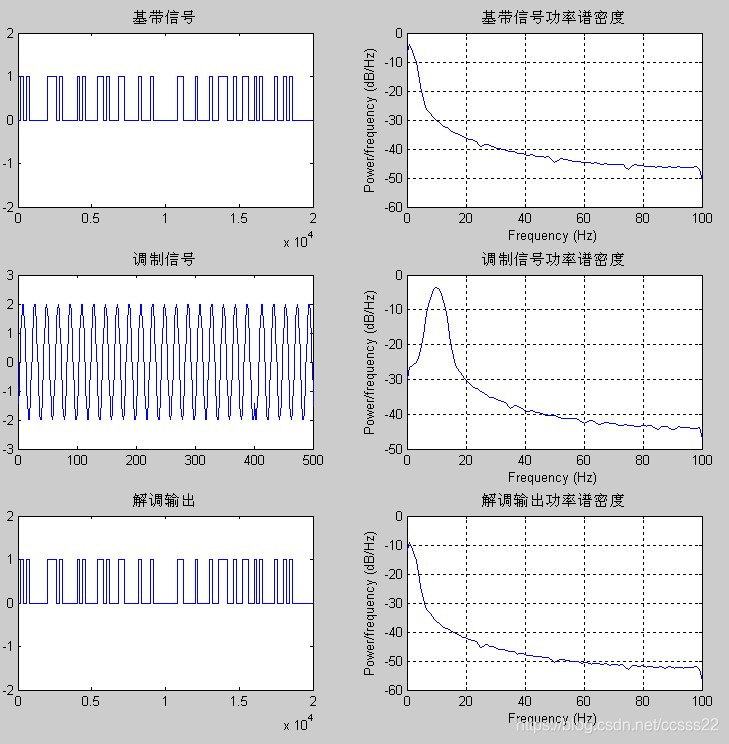
figure(1)
subplot(3,2,1);
plot(data0),title('基带信号');
axis([0 20000 -2 2]);
subplot(3,2,2);
psd(h,data1,'fs',fs),title('基带信号功率谱密度');
subplot(3,2,3);
plot(s),title('调制信号');
axis([0 500 -3 3]);
subplot(3,2,4);
psd(h,s,'fs',fs),title('调制信号功率谱密度');
subplot(3,2,5);
plot(demodata1),title('解调输出');
axis([0 20000 -2 2]);
subplot(3,2,6);
psd(h,demodata1,'fs',fs),title('解调输出功率谱密度');
%%%%%%%%%%%%%%%%%%%%%%%%%%%%%%%%%%%%%%%%%%%%%%%%%%%%%%%%
% 通过高斯信道
figure(2)
subplot(2,2,1);
plot(s1),title('调制信号(Awgn)');
axis([0 500 -5 5]);
subplot(2,2,2);
psd(h,s1,'fs',fs),title('调制信号功率谱密度(Awgn)');
subplot(2,2,3);
plot(s111),title('高斯噪声曲线');
axis([0 2000 -5 5]);
subplot(2,2,4);
for i=1:nb/2
plot(idata(i),qdata(i),'r+'),title('QPSK信号星座图(Awgn)');hold on;
axis([-2 2 -2 2]);
plot(Awgn_ichsum(i),Awgn_qchsum(i),'*');hold on;
legend('理论值(发射端)','实际值(接收端)');
end
%%%%%%%%%%%%%%%%%%%%%%%%%%%%%%%%%%%%%%%%%%%%%%%%%%%%%%%
%通过高斯信道再通过瑞利衰落信道
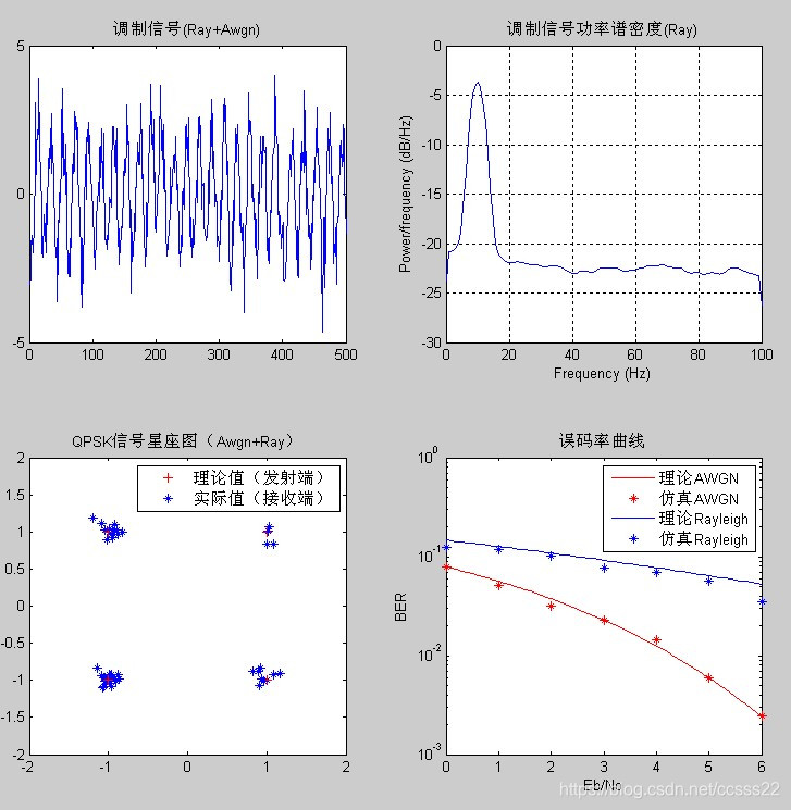
figure(3)
subplot(2,2,1)
plot(Ray_s),title('调制信号(Ray+Awgn)');
axis([0 500 -5 5]);
subplot(2,2,2);
psd(h,Ray_s,'fs',fs),title('调制信号功率谱密度(Ray)');
subplot(2,2,3);
for i=1:nb/2
plot(idata(i),qdata(i),'r+'),title('QPSK信号星座图(Awgn+Ray)');hold on;
axis([-2 2 -2 2]);
plot(Ray_ichsum(i),Ray_qchsum(i),'*');hold on;
legend('理论值(发射端)','实际值(接收端)');
end
subplot(2,2,4)
semilogy(SNRindB2,theo_err_awgn_prb,'r'),title('误码率曲线');hold on;
semilogy(SNRindB1,smld_bit_awgn_err_prb,'r*');hold on;
semilogy(SNRindB2,theo_err_ray_prb);hold on;
semilogy(SNRindB1,smld_bit_ray_err_prb,'*');
xlabel('Eb/No');ylabel('BER');
legend('理论AWGN','仿真AWGN','理论Rayleigh','仿真Rayleigh');
%文件2
function [pb,ps]=cm_sm32(snr_in_dB)
% [pb,ps]=cm_sm32(snr_in_dB)
% CM_SM3 finds the probability of bit error and symbol error for
% the given value of snr_in_dB, signal to noise ratio in dB.
N=100;
E=1; % energy per symbol
numofsymbolerror=0;
numofbiterror=0;
counter=0;
snr=10^(snr_in_dB/10); % signal to noise ratio
sgma=sqrt(E/snr)/2; % noise variance
s00=[1 0]; s01=[0 1]; s11=[-1 0]; s10=[0 -1]; % signal mapping
% generation of the data source
while(numofbiterror<100)
for i=1:N,
temp=rand; % a uniform random variable between 0 and 1
if (temp<0.25), % with probability 1/4, source output is "00"
dsource1(i)=0; dsource2(i)=0;
elseif (temp<0.5), % with probability 1/4, source output is "01"
dsource1(i)=0; dsource2(i)=1;
elseif (temp<0.75), % with probability 1/4, source output is "10"
dsource1(i)=1; dsource2(i)=0;
else % with probability 1/4, source output is "11"
dsource1(i)=1; dsource2(i)=1;
end;
end;
% detection and the probability of error calculation
for i=1:N,
ray=raylrnd(0.8);
n=sgma*randn(1,2); % 2 normal distributed r.v with 0, variance sgma
if ((dsource1(i)==0) & (dsource2(i)==0)),
r=ray*s00+n;
elseif ((dsource1(i)==0) & (dsource2(i)==1)),
r=ray*s01+n;
elseif ((dsource1(i)==1) & (dsource2(i)==0)),
r=s10*ray+n;
else
r=s11*ray+n;
end;
% The correlation metrics are computed below
c00=dot(r,s00); c01=dot(r,s01); c10=dot(r,s10); c11=dot(r,s11);
% The decision on the ith symbol is made next
c_max=max([c00,c01,c10,c11]);
if (c00==c_max), decis1=0; decis2=0;
elseif (c01==c_max), decis1=0; decis2=1;
elseif (c10==c_max), decis1=1; decis2=0;
else decis1=1; decis2=1;
end;
% Increment the error counter, if the decision is not correct
symbolerror=0;
if (decis1~=dsource1(i)), numofbiterror=numofbiterror+1; symbolerror=1;
end;
if (decis2~=dsource2(i)), numofbiterror=numofbiterror+1; symbolerror=1;
end;
if (symbolerror==1), numofsymbolerror=numofsymbolerror+1;
end;
end
counter=counter+1;
end
ps=numofsymbolerror/(N*counter); % since there are totally N symbols
pb=numofbiterror/(2*N*counter); % since 2N bits are transmitted
%文件3
function [pb1,ps1]=cm_sm32(snr_in_dB)
% [pb,ps]=cm_sm32(snr_in_dB)
% CM_SM3 finds the probability of bit error and symbol error for
% the given value of snr_in_dB, signal to noise ratio in dB.
N=100;
E=1; % energy per symbol
snr=10^(snr_in_dB/10); % signal to noise ratio
sgma=sqrt(E/snr)/2; % noise variance
s00=[1 0]; s01=[0 1]; s11=[-1 0]; s10=[0 -1]; % signal mapping
% generation of the data source
numofsymbolerror=0;
numofbiterror=0;
counter=0;
while(numofbiterror<100)
for i=1:N,
temp=rand; % a uniform random variable between 0 and 1
if (temp<0.25), % with probability 1/4, source output is "00"
dsource1(i)=0; dsource2(i)=0;
elseif (temp<0.5), % with probability 1/4, source output is "01"
dsource1(i)=0; dsource2(i)=1;
elseif (temp<0.75), % with probability 1/4, source output is "10"
dsource1(i)=1; dsource2(i)=0;
else % with probability 1/4, source output is "11"
dsource1(i)=1; dsource2(i)=1;
end;
end;
% detection and the probability of error calculation
for i=1:N,
% the received signal at the detection, for the ith symbol,is:
n=sgma*randn(1,2); % 2 normal distributed r.v with 0, variance sgma
if ((dsource1(i)==0) & (dsource2(i)==0)),
r=s00+n;
elseif ((dsource1(i)==0) & (dsource2(i)==1)),
r=s01+n;
elseif ((dsource1(i)==1) & (dsource2(i)==0)),
r=s10+n;
else
r=s11+n;
end;
% The correlation metrics are computed below
c00=dot(r,s00); c01=dot(r,s01); c10=dot(r,s10); c11=dot(r,s11);
% The decision on the ith symbol is made next
c_max=max([c00,c01,c10,c11]);
if (c00==c_max), decis1=0; decis2=0;
elseif (c01==c_max), decis1=0; decis2=1;
elseif (c10==c_max), decis1=1; decis2=0;
else decis1=1; decis2=1;
end;
% Increment the error counter, if the decision is not correct
symbolerror=0;
if (decis1~=dsource1(i)), numofbiterror=numofbiterror+1; symbolerror=1;
end;
if (decis2~=dsource2(i)), numofbiterror=numofbiterror+1; symbolerror=1;
end;
if (symbolerror==1), numofsymbolerror=numofsymbolerror+1;
end;
end
counter=counter+1;
end
ps1=numofsymbolerror/(N*counter); % since there are totally N symbols
pb1=numofbiterror/(2*N*counter); % since 2N bits are transmitted


 726
726

 被折叠的 条评论
为什么被折叠?
被折叠的 条评论
为什么被折叠?
 到【灌水乐园】发言


