


We now go in the meat of these tutorials. That's the real stuff. The one for big boys. This is where we will try to get a good understanding of the rendering process in Ogre and see how we can act upon it.
- back to list of tutorials
- Step A: understanding geometry in Ogre
- Step B: constructing your own mesh
- Step C: rendering with a Cg shader
- Step D: advanced parameter passing
- Going further...
Step A: understanding geometry in Ogre
Up to now we have used existing meshes that were build outside Ogre and exported to the .mesh format. Ogre provided the loading and rendering mechanisms through entities. That's great for populating the scene. But during rendering, there may be situations where you would want to generate some geometry on the fly. A good example is shadow quads in stenciled shadow volumes. We have already used the MeshManager in previous tutorial to create a simple plane. We will now see how to use this class to create meshes in a general way. For that I must first lecture you about meshes in Ogre. Fasten you seat belt and let's go.
Vertex data and materials
Let's start with how 3D models are described in Ogre. The most efficient way to describe 3D data for the graphic card is indexed face sets. This representation is composed of :
- an array of vertices with attributes (e.g. positions, colors, texture coordinates) which we refer to as vertex data;
- an array of indices, which we refer to as index data, that describe faces by listing the vertices (referenced by an index in first array) they pass through.
This decouples the vertices from the face connectivity, the benefit being that the graphic card can process vertices only once although the vertex is "traversed" several times for different faces it belongs to
Another important decoupling occurs. The indexed face set is just vertex and index data. To render it, we must also describe how to use this data. For example, we must indicate which texture the texture coordinates refer to. In Ogre's terminology, it means we must specify the material the model is to use with. The terminology might be confusing to you as some of the attributes -- for example color -- might be what you naturally think of as the material. What I can suggest you is to think of the material as the program indicating how the data is to be processed to render the model. Indeed, today's hardware offers the possibility to re-program the standard pipeline so semantic (i.e. vertex position, vertex color) inherited from this standard pipeline can be dropped in favor of generic "vertex attributes" (although we ususally stick to the old semantic as mnemotechnic helpers). Besides complex vertex or fragment programs, rendering may also involve several passes so material is really an important concept. We'll discuss it a bit more later.
To summarize, you can think of the vertex/index data as the "geometry" and of the material as the "appearance" although this vision of things is outdated with programmable hardware What you really have are "vertex attributes" send to "programs". By the way vertex and fragment programs are historically called shaders as they are typically used for (and were designed to) specify complex appearances (aka shading). Personnally I really see them as programs (and many people indeed use them for other things than rendering).
Meshes and sub-meshes
So we have seen there is data and program/material assembled to describe models to be rendered. In Ogre a model is called a mesh and the class that encapsulates this is Mesh. A mesh can represent arbitrary things but it usually describes a whole "object". Indeed, you could organize your scene in any way but for rendering efficiency and for ease of manipulation (e.g. to move things in the scene), you will prefer an organization per logical object (e.g. a character or a vehicle). A Mesh is such a logical unit, for example our robot. An important point is that such a unit is typically composed of differents parts with different materials although they may share some vertex data such as the 3D position. For that reason Ogre introduces the SubMesh class. A SubMesh has a unique material. A Mesh is a set of SubMesh as you would expect from the names.
Just a final note : if the SubMesh is really atomic and stores only vertex/index data, the Mesh is actually a bit more that a collection of sub-meshes. It also store information on which resource group it belongs to, what is its status (loaded, touched, etc.) and methods for shadow rendering.
Entities and sub-entities
One important point about materials is that they change more often than vertex/index data. What I mean here is that typically a scene contains similar object that are only different in their appearance. A good example is the cars in a racing game. In such cases, you want to share as much as you can. In particular, you would share the vertex and index data and only store a different material per instance. To offer such flexibility, Ogre has a layer about meshes and sub-meshes that are entities and sub-entities represented by the Entity and SubEntity classes. An Entity has a pointer to a Mesh but can overidde the materials of its sub-meshes. For that, it has a SubEntity per SubMesh of the pointed Mesh and each SubEntity stores its own material. Therefore, you will find a setMaterialName(...) method in the SubMesh and the SubEntity classes. If you call it for a submesh, you will impact all the entities that use them and if you call it for a subentity you will impact only this particular instance. Note that you also find a convenient (but at first confusing) setMaterialName(...) method in the Entity class. Here is what its API reference says :
The class Entity actually serves other purposes such as maintaining a bounding box and various flags about how it must be rendered (is it visible, does it cast shadows, etc.) or queried (for example in a ray/scene query). As we have seen, an Entity is itself attached to a scene node that holds information on how this particular instance of a mesh is placed in the scene.
Hardware buffers
To finish, let's describe how vertex/index data are specified in Ogre. Ogre is a platform for developing performant 3D applications. Thus, it uses state of the art (i.e. most efficient) mechanisms. Concerning vertex data, it means using hardware buffers. From the API reference of class HardwareBuffer :
Hardware buffers are efficient because they limit the (costly) transfers from the CPU to the GPU (the graphic card) and let the data exists as close as possible to where they will be used. There are various types of hardware buffers : vertex buffers, index buffers, texture memory or framebuffer memory etc. For the moment, we will focus on vertex and index buffers but the principles we'll discover are general.
The price to pay for that efficiency is twofold. First hardware buffers are much less flexible than system memory. Second, if the data is to be also used on the CPU (e.g. for collision detection) and not simply rendered, you might have memory duplication. From the API reference of HardwareBuffer :
So harware buffers involve some work and some knowledge from you, mainly because you must know the various type of access they define and decide which one is best suited to your particular situation. I am not going to detail them here as you can find dedicated tutorials on the web. As helpers, I repeat here the doc from Ogre API reference for the HardwareBuffer::LockOptions :
| HBL_NORMAL | Normal mode, ie allows read/write and contents are preserved. |
| HBL_DISCARD | Discards the entire buffer while locking; this allows optimisation to be performed because synchronisation issues are relaxed. Only allowed on buffers created with the HBU_DYNAMIC flag. |
| HBL_READ | _ONLY Lock the buffer for reading only. Not allowed in buffers which are created with HBU_WRITE_ONLY. Mandatory on statuc buffers, ie those created without the HBU_DYNAMIC flag. |
| HBL_NO_OVERWRITE | As HBL_NORMAL, except the application guarantees not to overwrite any region of the buffer which has already been used in this frame, can allow some optimisation on some APIs. |
And for the HardwareBuffer::Usage :
| HBU_STATIC | Static buffer which the application rarely modifies once created. Modifying the contents of this buffer will involve a performance hit. |
| HBU_DYNAMIC | Indicates the application would like to modify this buffer with the CPU fairly often. Buffers created with this flag will typically end up in AGP memory rather than video memory. |
| HBU_WRITE_ONLY | Indicates the application will never read the contents of the buffer back, it will only ever write data. Locking a buffer with this flag will ALWAYS return a pointer to new, blank memory rather than the memory associated with the contents of the buffer; this avoids DMA stalls because you can write to a new memory area while the previous one is being used. |
| HBU_DISCARDABLE | Indicates that the application will be refilling the contents of the buffer regularly (not just updating, but generating the contents from scratch), and therefore does not mind if the contents of the buffer are lost somehow and need to be recreated. This allows and additional level of optimisation on the buffer. This option only really makes sense when combined with HBU_DYNAMIC_WRITE_ONLY. |
| HBU_STATIC_WRITE_ONLY | Combination of HBU_STATIC and HBU_WRITE_ONLY. |
| HBU_DYNAMIC_WRITE_ONLY | Combination of HBU_DYNAMIC and HBU_WRITE_ONLY. If you use this, strongly consider using HBU_DYNAMIC_WRITE_ONLY_DISCARDABLE instead if you update the entire contents of the buffer very regularly. |
| HBU_DYNAMIC_WRITE_ONLY_DISCARDABLE | Combination of HBU_DYNAMIC, HBU_WRITE_ONLY and HBU_DISCARDABLE. |
Let's now see how (explicit) meshes construction is done in Ogre.
Step B: constructing your own mesh
Now that we have swept the concepts, let's work on an example: a dice mesh. The details of the mesh are shown on the figure below.
A first thing you should notice is that we have to repeat some vertices. Indeed, those vertices have the same position but not the same texture coordinates so they must be considered as two different points. That is one of the major drawbacks of (single) indexed face sets (if we could use multiple index per vertex attributes we would'nt have this limitation). To convince yourself, think of the normals. Consider for example vertex 0. Depending of which face you consider, it should have a different normal. So actually we should split our tri-faces in three and could not share any vertex! To make it simple, we consider vertex to have a normal pointing outward the origin (so the shading will be the one of a sphere).
A second thing to notice is that Ogre does not know about quads (actually, DirectX does not), so we must use triangles for the faces of our dice. This said, let's proceed to the code. We start up by declaring the raw data describing our mesh.
| 31 |
// Raw data
|
| 32 |
static
const
size_t nbVertices =
16;
|
| 33 |
static
const
size_t nbFaces =
12;
|
| 34 |
static
const
size_t nbVerticesPerFaces =
3;
|
| 35 |
static
const Vector3 positions
[nbVertices
] =
|
| 36 |
{
|
| 37 |
Vector3
(-
0.5f,-
0.5f,-
0.5f
),
|
| ............................ | |
| 53 |
};
|
| 54 |
static
const Vector2 tcoordinates
[nbVertices
] =
|
| 55 |
{
|
| 56 |
Vector2
(
0.0f,
1.0f
),
|
| ............................ | |
| 72 |
};
|
| 73 |
static
const
unsigned
short faces
[nbFaces
]
[nbVerticesPerFaces
] =
|
| 74 |
{
|
| 75 |
{
4,
6,
2
},
{
2,
0,
4
},
|
| ............................ | |
| 81 |
};
|
| ............................ | |
Then we create a mesh and some submesh. We will place the mesh in the group Custom. Since we will have only one material on our dice (we packed the texture for the faces in a single texture) we need only one submesh :
| 82 |
// Create a mesh
|
| 83 |
MeshPtr mesh = MeshManager::
getSingleton
(
).
createManual
(
"dice.mesh",
"Custom"
);
|
| 84 |
// We create a submesh per material
|
| 85 |
SubMesh* submesh = mesh->createSubMesh
(
);
|
| ............................ | |
Then we can create the vertex data. There are two subtle points. The first one is about line 87. We indicate that we do not share vertices. Indeed, submeshes of a same mesh are necessary for material changes, but it can happen that though the material changes, the vertex data don't (think of a sphere whose one hemisphere is yellow and the other one red: vertices'positions and normals are the same on the jointure of the two hemispheres).
The second point is concerning the new on line 88. Since we do not share the vertex data with an existing submesh, we must create our own. Up to there it's OK. The bad (IMHO) thing is that the data deletion is ensured by the submesh (look at Ogre source code and you will see) so contrary to our rule of thumb "Delete only what you've created with new", we should not delete the vertex data pointer ourselves.
| 86 |
// We must create the vertex data, indicating how many vertices there will be
|
| 87 |
submesh->useSharedVertices =
false;
|
| 88 |
submesh->vertexData =
new VertexData
(
);
|
| 89 |
submesh->vertexData->vertexStart =
0;
|
| 90 |
submesh->vertexData->vertexCount = nbVertices;
|
| ............................ | |
Next we must add a vertex declaration. This is a sort of "header" that will indicate what we intend to put in the vertex data.
| 91 |
// We must now declare what the vertex data contains
|
| 92 |
VertexDeclaration* declaration = submesh->vertexData->vertexDeclaration;
|
| 93 |
static
const
unsigned
short source =
0;
|
| 94 |
size_t offset =
0;
|
| 95 |
offset += declaration->addElement
(source,offset,VET_FLOAT3,VES_POSITION
).
getSize
(
);
|
| 96 |
offset += declaration->addElement
(source,offset,VET_FLOAT3,VES_NORMAL
).
getSize
(
);
|
| 97 |
offset += declaration->addElement
(source,offset,VET_FLOAT2,VES_TEXTURE_COORDINATES
).
getSize
(
);
|
| ............................ | |
Once this is done, we can create the hardware buffer by requesting the appropriate manager :
| 98 |
// We create the hardware vertex buffer
|
| 99 |
HardwareVertexBufferSharedPtr vbuffer =
|
| 100 |
HardwareBufferManager::
getSingleton
(
).
createVertexBuffer
(declaration->getVertexSize
(source
),
// == offset
|
| 101 |
submesh->vertexData->vertexCount,
// == nbVertices
|
| 102 |
HardwareBuffer::
HBU_STATIC_WRITE_ONLY
);
|
| ............................ | |
Next we can fill the buffer with our raw data by basically copying them. Note that we must be very careful because if we mess up this part, we will get dummy geometry or/and segfaults. Unfortunately, it is quite hard to debug vertex buffers, so be prudent. While copying the data, we record the bounding box of the mesh as it will be useful later on.
| 103 |
// No we get access to the buffer to fill it. During so we record the bounding box.
|
| 104 |
AxisAlignedBox aabox;
|
| 105 |
float* vdata = static_cast<float*>
(vbuffer->lock
(HardwareBuffer::
HBL_DISCARD
)
);
|
| 106 |
for
(
size_t i=
0;i<nbVertices;++i
)
|
| 107 |
{
|
| 108 |
// Position
|
| 109 |
Vector3 position =
20.0f*positions
[i
];
|
| 110 |
*vdata++ = position.
x;
|
| 111 |
*vdata++ = position.
y;
|
| 112 |
*vdata++ = position.
z;
|
| 113 |
aabox.
merge
(position
);
|
| 114 |
// Normal
|
| 115 |
Vector3 normal = position.
normalisedCopy
(
);
|
| 116 |
*vdata++ = normal.
x;
|
| 117 |
*vdata++ = normal.
y;
|
| 118 |
*vdata++ = normal.
z;
|
| 119 |
// Texture coordinate
|
| 120 |
Vector2 tcoordinate = tcoordinates
[i
];
|
| 121 |
*vdata++ = tcoordinate.
x;
|
| 122 |
*vdata++ = tcoordinate.
y;
|
| 123 |
}
|
| ............................ | |
Note on line 105 how we get access to the hardware buffer data area by locking it. Now that we have copied the data fomr the main memory to this data area, we can unlock it :
| 124 |
vbuffer->unlock
(
);
|
| ............................ | |
And we indicate which binding to use. Binding is an advanced concept of Ogre that I won't describe here (to be honest because I do not fully get the interest/application).
| 125 |
submesh->vertexData->vertexBufferBinding->setBinding
(source,vbuffer
);
|
| ............................ | |
Next we do the same process to create the index data.
| 126 |
// Creates the index data
|
| 127 |
submesh->indexData->indexStart =
0;
|
| 128 |
submesh->indexData->indexCount = nbFaces*nbVerticesPerFaces;
|
| 129 |
submesh->indexData->indexBuffer =
|
| 130 |
HardwareBufferManager::
getSingleton
(
).
createIndexBuffer
(HardwareIndexBuffer::
IT_16BIT,
|
| 131 |
submesh->indexData->indexCount,
|
| 132 |
HardwareBuffer::
HBU_STATIC_WRITE_ONLY
);
|
| 133 |
uint16* idata = static_cast<uint16*>
(submesh->indexData->indexBuffer->lock
(HardwareBuffer::
HBL_DISCARD
)
);
|
| 134 |
for
(
size_t i=
0;i<nbFaces;++i
)
|
| 135 |
{
|
| 136 |
for
(
size_t j=
0;j<nbVerticesPerFaces;++j
)
|
| 137 |
{
|
| 138 |
*idata++ = faces
[i
]
[j
];
|
| 139 |
}
|
| 140 |
}
|
| 141 |
submesh->indexData->indexBuffer->unlock
(
);
|
| ............................ | |
To finish there are three important steps. The first one took me a while to figure out: you must set the bounding box of the mesh. If you forget it, you get a blank screen syndrom. Note that the member function used starts with underscore which denotes functions that Ogre's developer have not made protected because in some cases you want to access them, although they want to highlight it should'nt occur too often. The two other steps are to indicate the mesh is loaded and to attribute it a (default) material.
| 142 |
// We must indicate the bounding box
|
| 143 |
mesh->_setBounds
(aabox
);
|
| 144 |
mesh->_setBoundingSphereRadius
(
(aabox.
getMaximum
(
)-aabox.
getMinimum
(
)
).
length
(
)/
2.
0
);
|
| 145 |
// Finally we set a material to the submesh
|
| 146 |
submesh->setMaterialName
(
"Tutorial4/Dice"
);
|
| 147 |
// And we load the mesh
|
| 148 |
mesh->load
(
);
|
| ............................ | |
We are finished with the creation of the mesh. Now we can use it as any other resource to create an entity.
| 150 |
// Create an entity with the mesh
|
| 151 |
Entity *entity = mSceneManager->createEntity
(
"Dice",
"dice.mesh"
);
|
| 152 |
SceneNode* node = mSceneManager->getRootSceneNode
(
)->createChildSceneNode
(
"DiceNode"
);
|
| 153 |
node->attachObject
(entity
);
|
| ............................ | |
Result
We now have a nice dice. Note that the faces are not that much distinguishable (e.g. constant color) because no shading takes place. First we have not set any light so the color of the mesh is only its ambient color blended with the texture. Second, even if we add a light, the face will appear weirdly lit because we set up the normal not per face but per vertex. Anyway, that was just a pdedagogical example, we won't use it anymore.
Saving the mesh for later reuse
Since it involves quite some code for generating the mesh, we would like to be able to save it for later reuse. This is done by requesting a MeshSerializer to do it. By default, it saves using the latest .mesh file format version (currently 1.3). the code is no simpler than :
| 153 |
node->attachObject
(entity
);
|
| 154 |
|
| 155 |
// Save the mesh for later reuse
|
| ............................ | |
Note that the "dice.mesh" above is the filename not the resource name we gave to mesh. We just happen to choose the same one for consistency! Of course, our application is dummy as it creates and saves the mesh everytime. It is just to show how to create an application that dumps some mesh (e.g. a fileformat converter or a scene generator/editor). Just a last remark : the .mesh file contains the name of the material "hard coded" in it. So if you want to later reload the mesh, you must be sure that the material is an available resource at that time.
Step C: rendering with a Cg shader
In the previous step, I have (voluntarily) skipped some details about materials. We will now go further about it. I won't go into the basics as you can find much information in Ogre's manual about material scripts. What we will see instead is how to use a Cg shader.
In that step, we will not work in the C++ code but instead with material scripts. Be sure you have brushed up your understanding of resource management with Tutorial 2. The code we will use is simply a display of a ninja with a moving light, very similar to the final program of Tutorial 3.
Introducing the different elements
Let's start with a simple Cg shader that displays the normal as color. This shader is useful if you want to shoot a normal map of a model (for example to bump map an impostor). Here is the code of the shader :
| 1 |
void main_vp
(in float4 position : POSITION,
|
| 2 |
in float3 normal : NORMAL,
|
| 3 |
out float4 oPosition : POSITION,
|
| 4 |
out float4 oColor : COLOR,
|
| 5 |
uniform float4x4 worldViewProj
)
|
| 6 |
{
|
| 7 |
// calculate output position
|
| 8 |
oPosition = mul
(worldViewProj, position
);
|
| 9 |
oColor.
rgb=
0.
5*normal+
0.
5;
|
| 10 |
oColor.
a =
1.
0;
|
| 11 |
}
|
| 12 |
|
| 13 |
void main_fp
(in float4 color : COLOR,
|
| 14 |
out float4 oColor : COLOR
)
|
| 15 |
{
|
| 16 |
oColor = color;
|
| 17 |
}
|
| 18 |
|
I assume you know how to read Cg programs. The only thing I want to point out is line 5 : the uniform parameter is something we have to pass from the C++ program to the shader using the appropriate API (for example cgGLSetParameter*(...) with OpenGL). Since Ogre is a wrapper independent of the API (DirectX or OpenGL), there must (and will) be a mechanism to specify these parameters. We will come back to it later. For the moment, let's see how we "register/declare" our Cg programs in Ogre. We do so by adding entries in an appropriate resource file. To declare the vertex program we put :
| 1 |
vertex_program Tutorial4/NormalMapVP cg
|
| 2 |
{
|
| 3 |
source normalmap.
cg
|
| 4 |
entry_point main_vp
|
| 5 |
profiles vs_
1_
1 arbvp1
|
| 6 |
}
|
| ............................ | |
How does it read? It says that :
- we declare a new resource named Tutorial4/NormalMapVP which is a vertex program of Cg type. From now on, we can refer to the program by this resource name. An important point is that Ogre guarantees that all .program resource are loaded before any .material resource is loaded so you should place this declaration either in a .program file (as we did) or first in .material file that uses it;
- the source for this vertex program is in file normalmap.cg which must be in the resource locations (not necessarily in same archive than the .material resource);
- the entry point in the source file for the vertex program function. This is a convenient functionnality of Cg which allows us to have both the vertex and fragment program in the same file, defined in two different "main" functions;
- the Cg compiler must try to compile the source with the following profiles, in the order given (see Cg tutorials for details on profiles); The idea here is that your list contains the most powerful profile down to the less powerful one that can compile the given Cg code. Ogre then tries to compile with the best profile. If it cannot, any technique (we will soon see what it is) that use this program will be ignored.
Profile is an important concept. If you want to know the profiles (or syntax in Ogre's terminology) supported by the card your program is ran on, you can do :
| 1 |
// Test which syntax are allowed for shaders
|
| 2 |
const GpuProgramManager::
SyntaxCodes &syntaxCodes = GpuProgramManager::
getSingleton
(
).
getSupportedSyntax
(
);
|
| 3 |
for
(GpuProgramManager::
SyntaxCodes::
const_iterator iter = syntaxCodes.
begin
(
);iter != syntaxCodes.
end
(
);++iter
)
|
| 4 |
{
|
| 5 |
LogManager::
getSingleton
(
).
logMessage
(
"supported syntax : "+
(*iter
)
);
|
| 6 |
}
|
| 7 |
|
Note however that you can run this for info but that you would usually not use it to dynamically select a profile. Indeed, the Ogre way of choosing between profiles is by specifying a list of profiles that support your program and letting Ogre choose the best one or ignore the program. You would typically specify at least a profile for OpenGL and one for DirectX.
Above we have seen the declaration of the vertex program. Declaring the fragment program is very similar :
| 8 |
fragment_program Tutorial4/NormalMapFP cg
|
| 9 |
{
|
| 10 |
source normalmap.
cg
|
| 11 |
entry_point main_fp
|
| 12 |
profiles ps_
1_
1 arbfp1
|
| 13 |
}
|
| ............................ | |
OK, so now the programs are available resources. So we can use them in a material.
Materials : the power of Ogre
We've been talking of materials a little bit across the previous tutorials. Let's go a bit deeper into it. Materials are an important part of Ogre since this defines (most of) the appearance of the rendering. It is also a difficult part as shading (the computer graphic term for appearance) potentially involves many techniques (Gouraud shading model or variant/extensions, texture mapping, shaders, multi-pass, etc.). In particular, when developping a game, you want it to work on different platforms/graphic cards with different capabilities so you must provide different ways of achieving a given effect to ensure one at least will match the platform/card capacities. Because it is important and difficult, the material section of the Ogre Manual is much more furnished than the other parts. I strongly recommand you get through at least once as I will just skim the basics now.
A material in Ogre is made of a list of techniques which serves the aforementionned purpose of describing various way of achieving a given effect (usually with various tradeoffs between efficiency and quality) so Ogre can gracefully degrade on any platform/card. A technique is itself composed of one or more passes, the simplest effects usually requesting only one (especially nowadays with programmable hardware). Ogre does some internal prioritizing of rendering according to materials and passes so it minimizes context switching (e.g. texture change) and guarantees a correct order for things like transparency. Each pass has a number of parameters specifying colors (ambient, diffuse, specular, etc.), texture units (which texture to use, how to map, etc.), various behaviour flags (is it subject to lighting, to shadowing, to z-buffering, etc.) and other aspects. Once again, refer to the material section of the Ogre Manual for exhaustive description. We will now only focus on program-related parameters.
Specifying a shader to use for a mesh
So we've declared our programs. Let's now use them in a material script :
| 1 |
material Tutorial4/NormalMap
|
| 2 |
{
|
| 3 |
technique
|
| 4 |
{
|
| 5 |
pass
|
| 6 |
{
|
| 7 |
vertex_program_ref Tutorial4/NormalMapVP
|
| 8 |
{
|
| 9 |
param_named_auto worldViewProj worldviewproj_matrix
|
| 10 |
}
|
| 11 |
fragment_program_ref Tutorial4/NormalMapFP
|
| 12 |
{
|
| 13 |
}
|
| 14 |
}
|
| 15 |
}
|
| 16 |
}
|
| ............................ | |
You should read the above declaration quite easily. It declares a resource named Tutorial4/NormalMap. It is a material with only one technique that involves only one pass. This pass uses both a vertex program and a fragment program and the one used are the one named respectively Tutorial4/NormalMapVP and Tutorial4/NormalMapFP. The only technical part is line 23. Remember earlier when I pointed out the uniform parameter in our Cg program? This is where it comes into play. Line 23 indicates that Ogre should automatically sets the value of the parameter named worldViewProj in the program source with the derived value named worldviewproj_matrix. This latest name is defined by Ogre and means (quite naturally) the product of the current modelview and projection matrices. You can find a list of the auto value defined by Ogre in the " 3.1.5 Using Vertex and Fragment Programs in a Pass" section of the Ogre manual.
Allright, this is all done for the material. Now we must simply overide the default material of the ninja mesh in our ninja entity. Remember what we have said earlier about this : we need to do this for the submeshes. The ninja model has two submeshes, one for the body one for the blade. We change only the first one :
| 34 |
// Overidde the default material for this instance of the mesh
|
| 35 |
ninja->getSubEntity
(
0
)->setMaterialName
(
"Tutorial4/NormalMap"
);
|
| ............................ | |
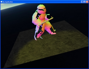
We can now run our program and here is the result : we can now see the normal of the faces on the body (the saber still has the metal-like material). It is quite hard to understand the colors for a human brain because the [-1,1] range is remapped to [0,1] but anyway it is not intended to be seen by humans!

Step D: advanced parameter passing
The previous shader we wrote was not that complex. Let's write a funnier one that makes the ninja and his saber "inflate"! For that, we will simply move vertices in the direction of their normal of an amount passed in parameters and varying with time. The shader is quite simple :
| 1 |
void main_vp
(in float4 position : POSITION,
|
| 2 |
in float3 normal : NORMAL,
|
| 3 |
out float4 oPosition : POSITION,
|
| 4 |
out float4 oColor : COLOR,
|
| 5 |
uniform float4x4 worldViewProj,
|
| 6 |
uniform
float
time,
|
| 7 |
uniform
float factor
)
|
| 8 |
{
|
| 9 |
// calculate output position
|
| 10 |
float4 p = position;
|
| 11 |
p.
xyz +=
(
1.
0+
time
)/
2.
0*factor*normal*p.
w;
|
| 12 |
oPosition = mul
(worldViewProj,p
);
|
| 13 |
oColor.
rgb=
0.
5*normal+
0.
5;
|
| 14 |
oColor.
a =
1.
0;
|
| 15 |
}
|
| 16 |
void main_fp
(in float4 color : COLOR,
|
| 17 |
out float4 oColor : COLOR
)
|
| 18 |
{
|
| 19 |
oColor = color;
|
| 20 |
}
|
| 21 |
|
The time parameter is supposed to take a value in [-1,1] (we'll see why in a moment). The factor can be any positive value. The effect of this shader is to move vertices in the direction of their normals by an amount controlled by these two parameters. Let's now declare these vertex and fragment programs :
| 1 |
vertex_program Tutorial4/InflateVP cg
|
| 2 |
{
|
| 3 |
source inflate.
cg
|
| 4 |
entry_point main_vp
|
| 5 |
profiles vs_
1_
1 arbvp1
|
| 6 |
default_params
|
| 7 |
{
|
| 8 |
param_named_auto worldViewProj worldviewproj_matrix
|
| 9 |
}
|
| 10 |
}
|
| 11 |
|
| 12 |
fragment_program Tutorial4/InflateFP cg
|
| 13 |
{
|
| 14 |
source inflate.
cg
|
| 15 |
entry_point main_fp
|
| 16 |
profiles ps_
1_
1 arbfp1
|
| 17 |
}
|
| 18 |
|
Compared to previous steps, what is new is the default_params section. What is it for? Let's declare the materials to understand it :
| 1 |
material Tutorial4/InflateBody
|
| 2 |
{
|
| 3 |
technique
|
| 4 |
{
|
| 5 |
pass
|
| 6 |
{
|
| 7 |
vertex_program_ref Tutorial4/InflateVP
|
| 8 |
{
|
| 9 |
param_named_auto time costime_
0_2pi
5
|
| 10 |
param_named factor
float
20
|
| 11 |
}
|
| 12 |
fragment_program_ref Tutorial4/InflateFP
|
| 13 |
{
|
| 14 |
}
|
| 15 |
}
|
| 16 |
}
|
| 17 |
}
|
| 18 |
material Tutorial4/InflateSaber
|
| 19 |
{
|
| 20 |
technique
|
| 21 |
{
|
| 22 |
pass
|
| 23 |
{
|
| 24 |
vertex_program_ref Tutorial4/InflateVP
|
| 25 |
{
|
| 26 |
param_named_auto time costime_
0_2pi
1
|
| 27 |
param_named factor
float
3
|
| 28 |
}
|
| 29 |
fragment_program_ref Tutorial4/InflateFP
|
| 30 |
{
|
| 31 |
}
|
| 32 |
}
|
| 33 |
}
|
| 34 |
}
|
| 35 |
|
We now define two materials that use the inflate shaders with two different set of params. The first thing to notice is that we do not have to define how the worldViewProj param is automatically "set" in the vertex_program sections of each material. This is because we have defined it by default in the vertex program declaration. The goal of the default_params section is now clear : it saves some lines in material declaration. Is it particularly useful if a shader is to be used in many different materials with varying other param.
Let's now look at the other two params declaration in InflateBody. The first one has to effect that time is automatically set to the cosinus of a ramp function of amplitute [0,2pi] and period 5 seconds. The second declaration sets the factor to a fixed value. For InflateSaber we use a period of 1 second and a factor of 3.
Finally, we set these two materials, this time also changing the material of the saber submesh :
| 34 |
// Overidde the default material for this instance of the mesh
|
| 35 |
ninja->getSubEntity
(
0
)->setMaterialName
(
"Tutorial4/InflateBody"
);
|
| 36 |
ninja->getSubEntity
(
1
)->setMaterialName
(
"Tutorial4/InflateSaber"
);
|
| ............................ | |
We also disabled the shadows in this step because stenciled shadow are messed up if the vertices are displaced on the GPU (i.e. in a vertex program) because shadow volumes are computed on the CPU that is without knowing the to-be-applied displacement (for info, the exception is GPU based skeleton animation/skinning because Ogre takes care of reflecting displacement on the CPU).
The result of the two materials declared is that the ninja will seem to inflate over time with various amplitudes/periods for the body and blades as shown on screenshots below. Quite useless but it was just a pedagogical tour!

Going further...
Have a look at :
- the CelShading example in Ogre's distribution
- read the material section of the Ogre Manual


 763
763

 被折叠的 条评论
为什么被折叠?
被折叠的 条评论
为什么被折叠?
 到【灌水乐园】发言


