


驱动直流电机的具体原理就不讲了 只提两个点
占空比越大,所得到的平均电压也就越大,幅值也就越大;占空比越小,所得到的平均电压也就越小,幅值也就越小。
直流电机的正转,反转和你电源的正接反接有关
PWM.c
#include "stm32f10x.h"                  // Device header

void PWM_Init(void)
{
	RCC_APB1PeriphClockCmd(RCC_APB1Periph_TIM2, ENABLE);
	RCC_APB2PeriphClockCmd(RCC_APB2Periph_GPIOA, ENABLE);

	GPIO_InitTypeDef GPIO_InitStructure;
	GPIO_InitStructure.GPIO_Mode = GPIO_Mode_AF_PP;
	GPIO_InitStructure.GPIO_Pin = GPIO_Pin_2;
	GPIO_InitStructure.GPIO_Speed = GPIO_Speed_50MHz;
	GPIO_Init(GPIOA, &GPIO_InitStructure);

	TIM_InternalClockConfig(TIM2);

	TIM_TimeBaseInitTypeDef TIM_TimeBaseInitStructure;
	TIM_TimeBaseInitStructure.TIM_ClockDivision = TIM_CKD_DIV1;
	TIM_TimeBaseInitStructure.TIM_CounterMode = TIM_CounterMode_Up;
	TIM_TimeBaseInitStructure.TIM_Period = 100 - 1;		//ARR
	TIM_TimeBaseInitStructure.TIM_Prescaler = 36 - 1;		//PSC
	TIM_TimeBaseInitStructure.TIM_RepetitionCounter = 0;
	TIM_TimeBaseInit(TIM2, &TIM_TimeBaseInitStructure);

	TIM_OCInitTypeDef TIM_OCInitStructure;
	TIM_OCStructInit(&TIM_OCInitStructure);
	TIM_OCInitStructure.TIM_OCMode = TIM_OCMode_PWM1;
	TIM_OCInitStructure.TIM_OCPolarity = TIM_OCPolarity_High;
	TIM_OCInitStructure.TIM_OutputState = TIM_OutputState_Enable;
	TIM_OCInitStructure.TIM_Pulse = 0;		//CCR
	TIM_OC3Init(TIM2, &TIM_OCInitStructure);

	TIM_Cmd(TIM2, ENABLE);
}

void PWM_SetCompare3(uint16_t Compare)
{
	TIM_SetCompare3(TIM2, Compare);
}
代码的变动不大,就是一个PWM
Motor.c
#include "stm32f10x.h"                  // Device header
#include "PWM.h"

void Motor_Init(void)
{
	RCC_APB2PeriphClockCmd(RCC_APB2Periph_GPIOA, ENABLE);

	GPIO_InitTypeDef GPIO_InitStructure;
	GPIO_InitStructure.GPIO_Mode = GPIO_Mode_Out_PP;
	GPIO_InitStructure.GPIO_Pin = GPIO_Pin_4 | GPIO_Pin_5;
	GPIO_InitStructure.GPIO_Speed = GPIO_Speed_50MHz;
	GPIO_Init(GPIOA, &GPIO_InitStructure);

	PWM_Init();
}

void Motor_SetSpeed(int8_t Speed)
{
	if (Speed >= 0)
	{
		GPIO_SetBits(GPIOA, GPIO_Pin_4);
		GPIO_ResetBits(GPIOA, GPIO_Pin_5);
		PWM_SetCompare3(Speed);
	}
	else
	{
		GPIO_ResetBits(GPIOA, GPIO_Pin_4);
		GPIO_SetBits(GPIOA, GPIO_Pin_5);
		PWM_SetCompare3(-Speed);
	}
}
这边选的是PA4和PA5作为输入接口控制电机的正反转,通过speed的值控制正反
Key.c用的是之前的舵机驱动的代码
mian.c
#include "stm32f10x.h"                  // Device header
#include "Delay.h"
#include "OLED.h"
#include "Motor.h"
#include "Key.h"

uint8_t KeyNum;
int8_t Speed;

int main(void)
{
	OLED_Init();
	Motor_Init();
	Key_Init();

	OLED_ShowString(1, 1, "Speed:");

	while (1)
	{
		KeyNum = Key_GetNum();
		if (KeyNum == 11)
		{
			Speed += 10;
			if (Speed > 100)
			{
				Speed = -100;
			}
		}
		else if (KeyNum == 12)
		{
			Speed -= 10;
			if (Speed < -100)
			{
				Speed = 100;
			}
		}
		else if (KeyNum == 1)
		{
			Speed += 1;
			if (Speed > 100)
			{
				Speed = -100;
			}
		}
		else if (KeyNum == 2)
		{
			Speed -= 1;
			if (Speed < -100)
			{
				Speed = 100;
			}
		}
		Motor_SetSpeed(Speed);
		OLED_ShowSignedNum(1, 7, Speed, 3);
	}
}
主要代码就这些了
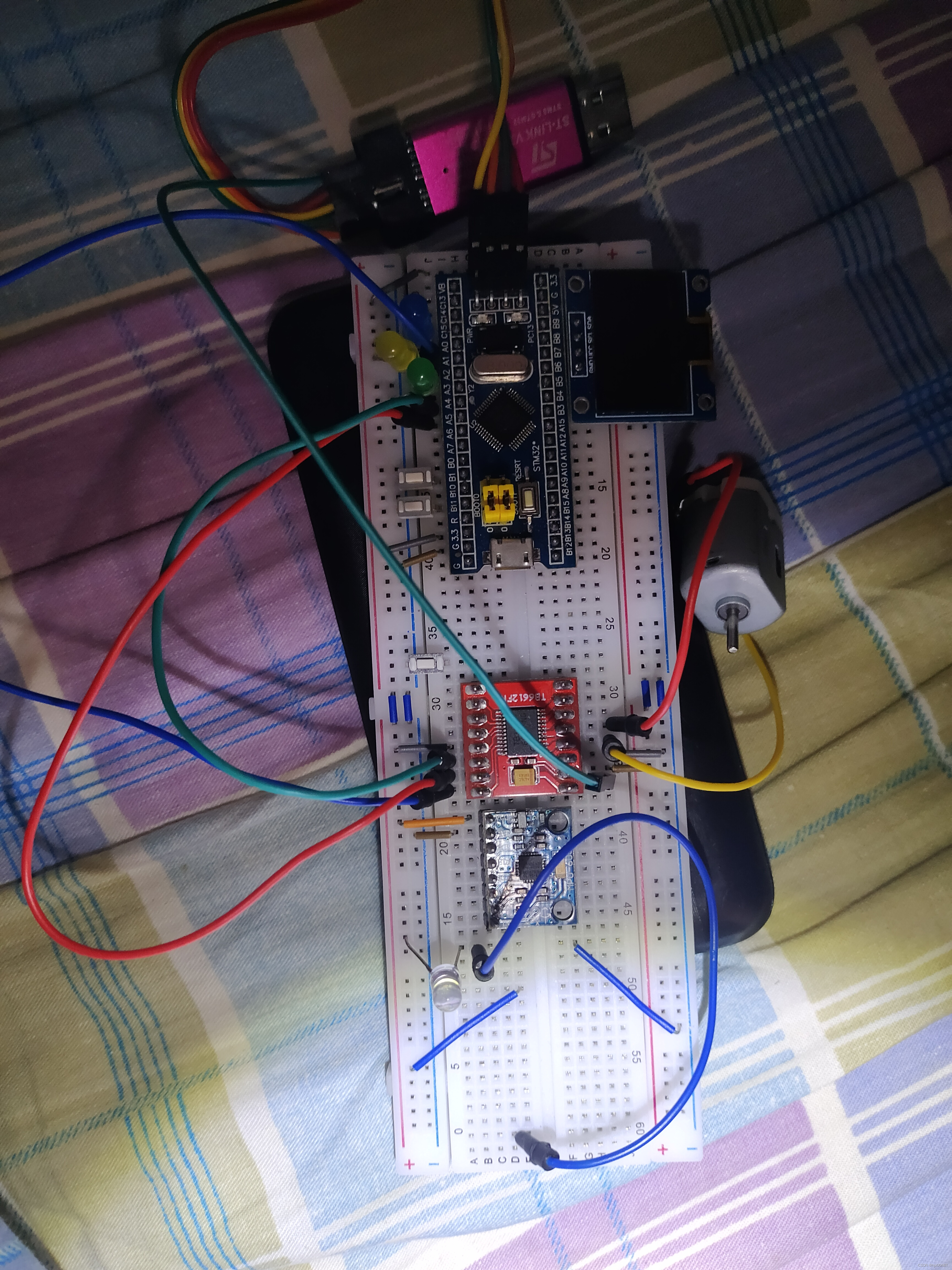
接线图
嘉立创没找到同型号的电调,所以用实物图了
演示


 7232
7232

 被折叠的 条评论
为什么被折叠?
被折叠的 条评论
为什么被折叠?
 到【灌水乐园】发言


