


项目场景:
在运用的过程中需要去操作到FLASH的时候
例如 1:将数据存放到FLASH中或者取出来
2:通过SPI去实现逻辑程序的更新
问题描述
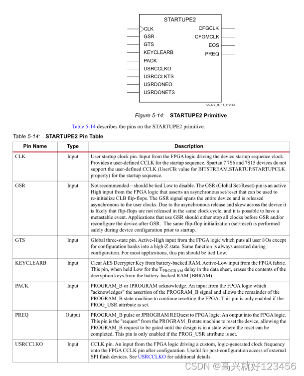
在项目开始的时候由于不知道FPGA和FLASH直接的SPI时钟管脚是用的CCLK时钟管脚,导致一直没有办法去操作FLASH中的数据。返回去查看原理图的时候发现管脚是专用时钟管脚,查阅XILINX的资料 UG470发现需要用 STARTUPE2 原语进行“使能”才可以进行操作
原因分析:
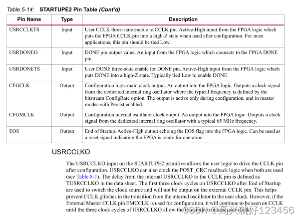
根据UG470文件描述CCLK为专用时钟管脚,当作普通管脚使用的时候需要进行使能。文件对原语的描述如下:
解决方案:
其中CCLK需要设置为 inout 类型,输入连接到 STARTUPE2 中,输出由逻辑自己实现控制
STARTUPE2 的控制如下就行:
STARTUPE2 #(
.PROG_USR(“FALSE”), // Activate program event security feature. Requires encrypted bitstreams.
.SIM_CCLK_FREQ(0.0) // Set the Configuration Clock Frequency(ns) for simulation.
)
STARTUPE2_inst (
.CFGCLK ( ), // 1-bit output: Configuration main clock output
.CFGMCLK ( ), // 1-bit output: Configuration internal oscillator clock output
.EOS ( ), // 1-bit output: Active high output signal indicating the End Of Startup.
.PREQ ( ), // 1-bit output: PROGRAM request to fabric output
.CLK ( 0 ), // 1-bit input: User start-up clock input
.GSR ( 0 ), // 1-bit input: Global Set/Reset input (GSR cannot be used for the port name)
.GTS ( 0 ), // 1-bit input: Global 3-state input (GTS cannot be used for the port name)
.KEYCLEARB ( 1 ), // 1-bit input: Clear AES Decrypter Key input from Battery-Backed RAM (BBRAM)
.PACK ( 1 ), // 1-bit input: PROGRAM acknowledge input
.USRCCLKO ( cclk ), // 1-bit input: User CCLK input
// For Zynq-7000 devices, this input must be tied to GND
.USRCCLKTS ( 0 ), // 1-bit input: User CCLK 3-state enable input
// For Zynq-7000 devices, this input must be tied to VCC
.USRDONEO ( 1 ), // 1-bit input: User DONE pin output control
.USRDONETS ( 1 ) // 1-bit input: User DONE 3-state enable output
);


 255
255

 被折叠的 条评论
为什么被折叠?
被折叠的 条评论
为什么被折叠?
 到【灌水乐园】发言


