


参考时钟50Mhz,检测时钟为 1-200Mhz,写出Verilog来。
一、设计
module clock_test
//========================< 参数 >==========================================
#(
parameter CLK_S_FRE = 31'd50 , // 基准时钟频率值
parameter GATE_TIME = 31'd5000 // 门控时间设置
)
//========================< 端口 >==========================================
(
input clk_s , // 基准时钟信号
input rst_n , // 复位信号
input clk_x , // 被测时钟信号
output reg [31:0] data_x // 被测时钟频率输出
);
//========================< 信号 >==========================================
reg [31:0] gate_cnt ;
reg gate ;
reg gate_s_r1 ;
reg gate_s_r2 ;
reg gate_x_r1 ;
reg gate_x_r2 ;
reg [31:0] s_cnt ;
reg [31:0] s_cnt_r ;
reg [31:0] x_cnt ;
reg [31:0] x_cnt_r ;
wire neg_gate_s ;
wire neg_gate_x ;
//==========================================================================
//== ________________ _______________
//== gate门控 ___| |___| |____
//== gate_cnt 0 1 5000 0 1 5000
//==========================================================================
always @(posedge clk_x or negedge rst_n) begin
if(!rst_n)
gate_cnt <= 'd0;
else if(gate_cnt == GATE_TIME + 20)//计数到+20,其中+20时间为低电平
gate_cnt <= 'd0;
else
gate_cnt <= gate_cnt + 1'b1;
end
always @(posedge clk_x or negedge rst_n) begin
if(!rst_n)
gate <= 1'b0;
else if(gate_cnt < GATE_TIME)
gate <= 1'b1;
else
gate <= 1'b0;
end
//==========================================================================
//== 打拍检测下降沿
//==========================================================================
always @(posedge clk_s) begin
gate_s_r1 <= gate;
gate_s_r2 <= gate_s_r1;
end
always @(posedge clk_x) begin
gate_x_r1 <= gate;
gate_x_r2 <= gate_x_r1;
end
assign neg_gate_s = gate_s_r2 & (~gate_s_r1);
assign neg_gate_x = gate_x_r2 & (~gate_x_r1);
//==========================================================================
//== 门控下的计数
//==========================================================================
always @(posedge clk_s or negedge rst_n) begin
if(!rst_n) begin
s_cnt <= 'd0; s_cnt_r <= 'd0;
end
else if(neg_gate_s) begin
s_cnt <= 'd0; s_cnt_r <= s_cnt;
end
else if(gate_s_r1) begin
s_cnt <= s_cnt + 1'b1;
end
end
always @(posedge clk_x or negedge rst_n) begin
if(!rst_n) begin
x_cnt <= 'd0; x_cnt_r <= 'd0;
end
else if(neg_gate_x) begin
x_cnt <= 'd0; x_cnt_r <= x_cnt;
end
else if(gate_x_r1) begin
x_cnt <= x_cnt + 1'b1;
end
end
//==========================================================================
//== 输出频率值
//==========================================================================
always @(posedge clk_s or negedge rst_n) begin
if(!rst_n) begin
data_x <= 'd0;
end
else if(~gate_s_r2 & gate_s_r1) begin
data_x <= (CLK_S_FRE * x_cnt_r ) / s_cnt_r;
end
end
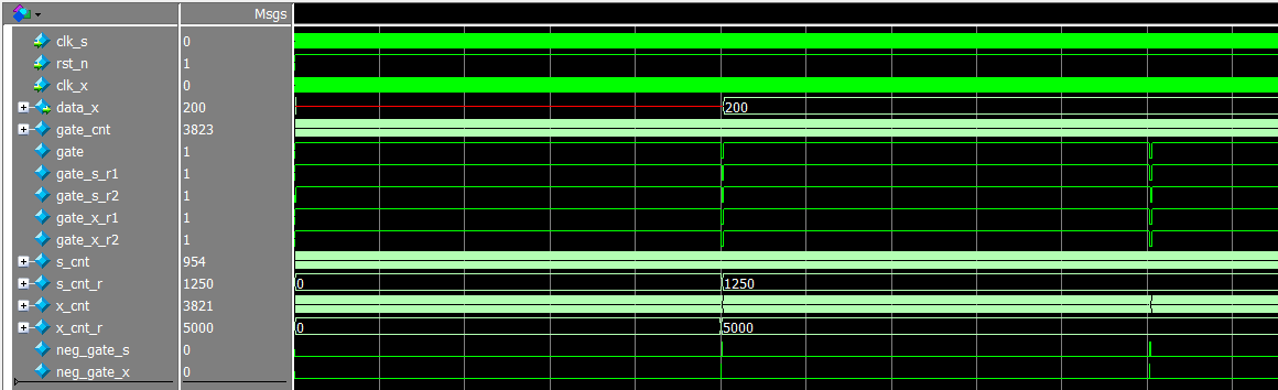
endmodule二、仿真
`timescale 1ns/1ps      //时间精度

module clock_test_tb;
//========================< 端口 >==========================================
reg                         clk_s                   ; //时钟,50Mhz
reg                         rst_n                   ; //复位,高电平有效
reg                         clk_x                   ; //2分频时钟

//==========================================================================
//==    模块例化
//==========================================================================
clock_test u_clock_test
(
    .clk_s                  (clk_s                  ),
    .rst_n                  (rst_n                  ),
    .clk_x                  (clk_x                  ),
    .data_x                 (                       )
);
//==========================================================================
//==    时钟信号和复位信号
//==========================================================================
initial begin
    clk_s = 1;
    forever
    #10 clk_s = ~clk_s;     //50Mhz
end

initial begin
    clk_x = 1;
    forever
    #2.5 clk_x = ~clk_x;    //200Mhz
end

initial begin
    rst_n = 0; #(41);
    rst_n = 1;
end


endmodule
二、仿真


 2085
2085

 被折叠的 条评论
为什么被折叠?
被折叠的 条评论
为什么被折叠?
 到【灌水乐园】发言


