


三、Circuits
Combinational logic-Karnaugh Map to Circuit
1、3-variable
Problem Statement:
mplement the circuit described by the Karnaugh map below.

module top_module(
    input a,
    input b,
    input c,
    output out
);
    assign out = a | b | c;

endmodule
2、4-variable
Problem Statement:
Implement the circuit described by the Karnaugh map below.

module top_module(
    input a,
    input b,
    input c,
    input d,
    output out
);
    assign out = ~a & ~d | ~b & ~c | b & c & d | a & ~b & d | ~a & b & c;

endmodule
3、4-variable
Problem Statement:
Implement the circuit described by the Karnaugh map below.

module top_module(
    input a,
    input b,
    input c,
    input d,
    output out
);
    assign out = a | ~b & c;

endmodule
4、4-variable
Problem Statement:
Implement the circuit described by the Karnaugh map below.

module top_module(
    input a,
    input b,
    input c,
    input d,
    output out
);
    assign out = a^b^c^d;

endmodule
5、Minimum SOP and POS
Problem Statement:
A single-output digital system with four inputs (a,b,c,d) generates a logic-1 when 2, 7, or 15 appears on the inputs, and a logic-0 when 0, 1, 4, 5, 6, 9, 10, 13, or 14 appears. The input conditions for the numbers 3, 8, 11, and 12 never occur in this system. For example, 7 corresponds to a,b,c,d being set to 0,1,1,1, respectively.
Determine the output out_sop in minimum SOP form, and the output out_pos in minimum POS form.
module top_module (
    input a,
    input b,
    input c,
    input d,
    output out_sop,
    output out_pos
);
    assign out_sop = c & d | ~a & ~ b & c;
    assign out_pos = ~((~c | ~d) & (a | b | ~c));

endmodule
6、Karnaugh map
Problem Statement:
Consider the function f shown in the Karnaugh map below.
Implement this function. d is don't-care, which means you may choose to output whatever value is convenient.

module top_module (
    input [4:1] x,
    output f
);
    assign f = ~x[1] & x[3] | x[2] & x[4];

endmodule
7、Karnaugh map
Problem Statement:
Consider the function f shown in the Karnaugh map below. Implement this function.
(The original exam question asked for simplified SOP and POS forms of the function.)
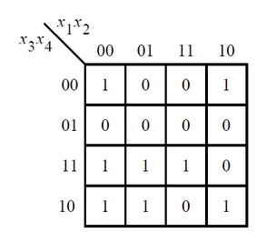
module top_module (
    input [4:1] x,
    output f
);
    assign f = ~x[1]&x[3] | ~x[2]&~x[4] | x[2]&x[3]&x[4];

endmodule
8、K-map implemented with a multiplexer
Problem Statement:
For the following Karnaugh map, give the circuit implementation using one 4-to-1 multiplexer and as many 2-to-1 multiplexers as required, but using as few as possible. You are not allowed to use any other logic gate and you must use a and b as the multiplexer selector inputs, as shown on the 4-to-1 multiplexer below.
You are implementing just the portion labelled top_module, such that the entire circuit (including the 4-to-1 mux) implements the K-map.


module top_module (
    input c,
    input d,
    output [3:0] mux_in
);

    always @(*) begin
        case({c,d})
            2'b00:
                mux_in = 4'b0100;
            2'b01:
                mux_in = 4'b0001;
            2'b11:
                mux_in = 4'b1001;
            2'b10:
                mux_in = 4'b0101;
            default:;
        endcase
    end

endmodule


 366
366


 被折叠的 条评论
为什么被折叠?
被折叠的 条评论
为什么被折叠?
 到【灌水乐园】发言


