


 文章展示了如何使用Verilog语言进行二进制补码转换的模块设计,包括正数和负数的补码表示。同时,提到了7段数码管译码器的相关内容。通过一个测试bench演示了补码转换的逻辑过程,并提供了波形图作为验证。
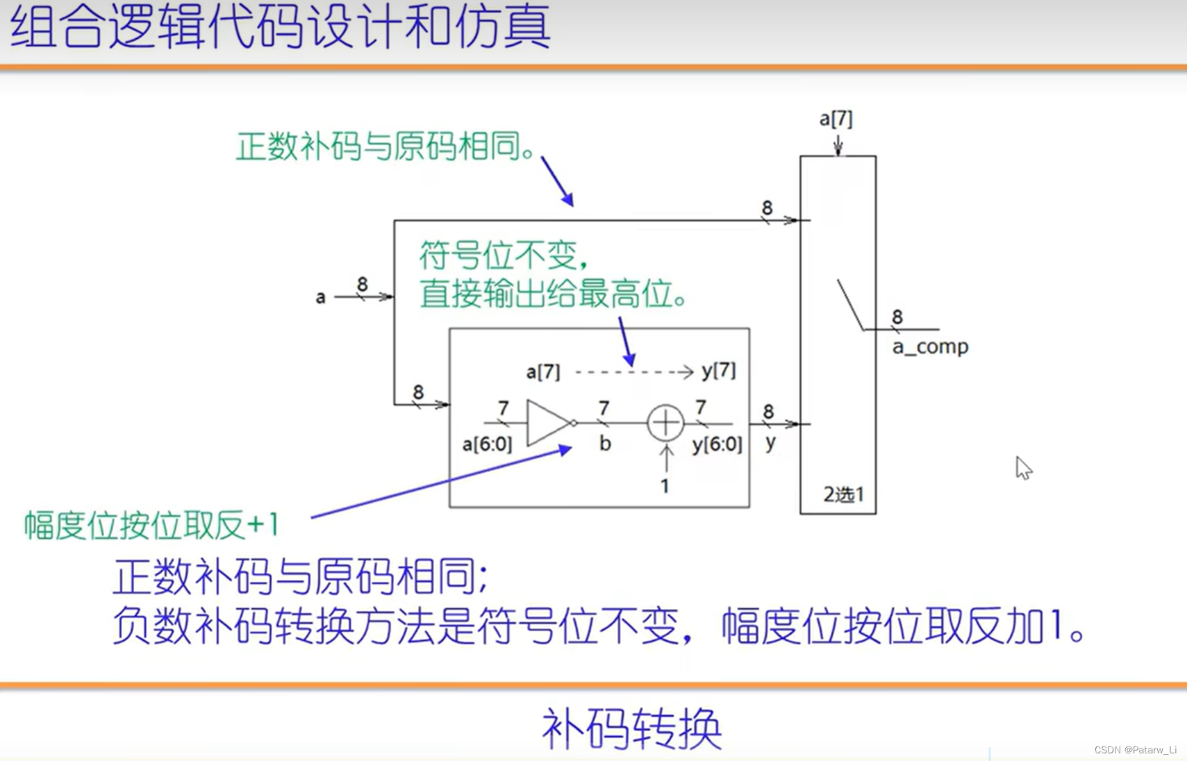
一、补码转换
verilog代码:
//2023/3/28 lzp
//二进制补码转换
`timescale 1ns/10ps
module complement_transfer(b_num, b_complement_num);
input[7:0] b_num;
output[7:0] b_complement_num;

reg[7:0] b_complement_num;

always@(b_num) begin
    if(b_num[7] == 0) begin
        //正数补码与原码相同
        b_complement_num<=b_num;
    end
    else if(b_num[7] == 1) begin
        //负数补码为符号不变,其余按位取反加1
        b_complement_num[7]=b_num[7];
        b_complement_num[6:0]=~b_num[6:0]+1;
    end
end

endmodule

//二进制补码转换testbench
module complement_transfer_tb;
reg[7:0] B_num;
wire[7:0] B_complement_num;

complement_transfer complement_transfer(.b_num(B_num), .b_complement_num(B_complement_num));

initial begin
    B_num<=8'b00000001;
    #2;
    B_num<=8'b10000001;
    #2;
    $stop;
end

endmodule
波形图:
 最低0.47元/天 解锁文章


 1万+
1万+

 被折叠的 条评论
为什么被折叠?
被折叠的 条评论
为什么被折叠?
 到【灌水乐园】发言


