


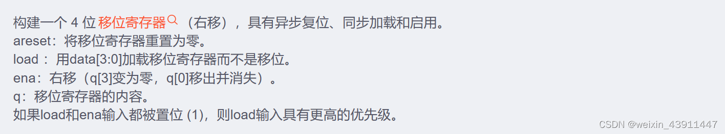
1. 4位移位寄存器 4-bit shift register
module top_module(
    input clk,
    input areset,  // async active-high reset to zero
    input load,
    input ena,
    input [3:0] data,
    output reg [3:0] q);

    always@(posedge clk or posedge areset)
        begin

            if(areset)
                   q<=4'b0;
            else if(load)
                q<=data;
            else if(ena)
                   q<={1'b0,q[3:1]};
            else
                   q<=q;
        end
endmodule
module top_module(
input clk,
input areset,
input load,
input ena,
input [3:0] data,
output reg [3:0] q);
// Asynchronous reset: Notice the sensitivity list.
// The shift register has four modes:
// reset
// load
// enable shift
// idle -- preserve q (i.e., DFFs)
always @(posedge clk, posedge areset) begin
if (areset) // reset
q <= 0;
else if (load) // load
q <= data;
else if (ena) // shift is enabled
q <= q[3:1]; // Use vector part select to express a shift.
end
endmodule
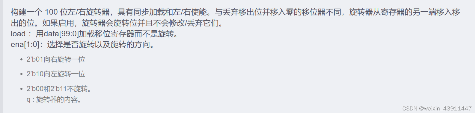
2. Left/ right register 左移|右移寄存器(1位)
module top_module(
    input clk,
    input load,
    input [1:0] ena,
    input [99:0] data,
    output reg [99:0] q);

    always@(posedge clk) begin
        if(load)            // load
            q<=data;
        else case(ena)      //  ena
            2'b00: q<=q;
            2'b01:q<={q[0],q[99:1]};  //右移
            2'b10:q<={q[98:0],q[99]}; //左移
            2'b11:q<=q;
            default;
        endcase
    end

endmodule
module top_module(
input clk,
input load,
input [1:0] ena,
input [99:0] data,
output reg [99:0] q);
always@(posedge clk) begin
if(load) // load
q<=data;
else case(ena) // ena
2'b00: q<=q;
2'b01:q<={q[0],q[99:1]}; //右移
2'b10:q<={q[98:0],q[99]}; //左移
2'b11:q<=q;
default;
endcase
end
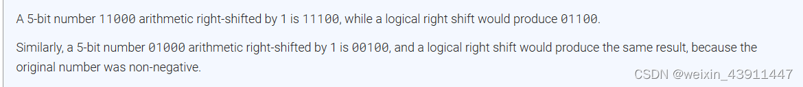
endmodule3. Left/right arithmetic shift by 1 or 8 算数 左移|右移寄存器(1 或8位)


module top_module(
input clk,
input load,
input ena,
input [1:0] amount,
input [63:0] data,
output reg [63:0] q);
//左移:算数左移==逻辑左移,丢弃高位,低位补0
//算数右移:丢弃低位,高位补符号位
//逻辑右移:丢弃低位,高位补0
always@(posedge clk) begin
if(load)
q<=data;
else if(ena)
begin
case(amount)
2'b00:q<={q[62:0],1'b0}; //左移,空位补0,丢弃高位,低位补0
2'b01:q<={q[55:0],8'b0}; //左移,空位补0,丢弃高位,低位补0
2'b10:q<={q[63],q[63:1]}; //算数右移,空位补最高位符号位
2'b11:q<={{8{q[63]}},q[63:8]}; //算术右移,空位补最高位符号位
endcase
end
else q<=q;
end
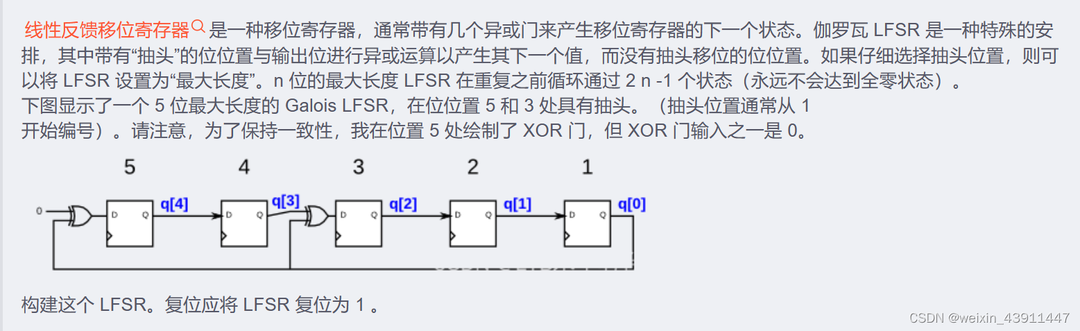
endmodule4. 5-bit LFSR
module top_module(
	input clk,
	input reset,
	output reg [4:0] q);

	reg [4:0] q_next;		// q_next is not a register

	// Convenience: Create a combinational block of logic that computes
	// what the next value should be. For shorter code, I first shift
	// all of the values and then override the two bit positions that have taps.
	// A logic synthesizer creates a circuit that behaves as if the code were
	// executed sequentially, so later assignments override earlier ones.
	// Combinational always block: Use blocking assignments.
	always @(*) begin
		q_next = q[4:1];	// Shift all the bits. This is incorrect for q_next[4] and q_next[2]
		q_next[4] = q[0];	// Give q_next[4] and q_next[2] their correct assignments
		q_next[2] = q[3] ^ q[0];
	end


	// This is just a set of DFFs. I chose to compute the connections between the
	// DFFs above in its own combinational always block, but you can combine them if you wish.
	// You'll get the same circuit either way.
	// Edge-triggered always block: Use non-blocking assignments.
	always @(posedge clk) begin
		if (reset)
			q <= 5'h1;
		else
			q <= q_next;
	end

endmodule
module top_module(
input clk,
input reset, // Active-high synchronous reset to 5'h1
output [4:0] q
);
always@(posedge clk)begin
if(reset) q<=5'b1;
else
q<={0^q[0],q[4],q[3]^q[0],q[2],q[1]};
end
endmodule5. 3-bit LFSR
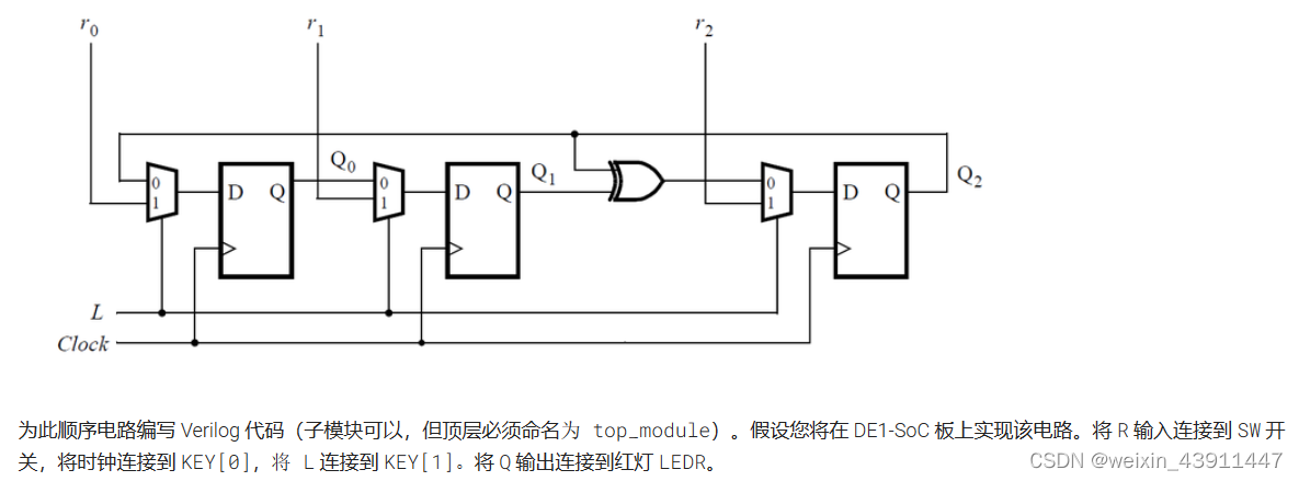
module top_module (
	input [2:0] SW,      // R
	input [1:0] KEY,     // L and clk
	output [2:0] LEDR);  // Q

    LFSR u_0(SW[0],KEY[1],KEY[0],LEDR[2],LEDR[0]);
    LFSR u_1(SW[1],KEY[1],KEY[0],LEDR[0],LEDR[1]);
    LFSR u_2(SW[2],KEY[1],KEY[0],LEDR[1]^LEDR[2],LEDR[2]);


endmodule


module LFSR(
    input r,
    input L,
    input clk,
    input Q,
    output q);
    always@(posedge clk)
        begin
            q <= L? r:Q ;
        end
endmodule
module top_module (
input [2:0] SW, // R
input [1:0] KEY, // L and clk
output [2:0] LEDR); // Q
reg ry;
assign ry=LEDR[1]^LEDR[2];
mode_muxdff u0(KEY[0],KEY[1],SW[0],LEDR[2],LEDR[0]);
mode_muxdff u1(KEY[0],KEY[1],SW[1],LEDR[0],LEDR[1]);
mode_muxdff u2(KEY[0],KEY[1],SW[2],ry,LEDR[2]);
endmodule
module mode_muxdff (
input clk,
input L,
input r_in,
input q_in,
output reg Q);
wire D;
assign D=L? r_in:q_in;
always @(posedge clk)
begin
Q<=D;
end
endmodule
6. 32-bit LFSR

module top_module(
    input clk,
    input reset,    // Active-high synchronous reset to 32'h1
    output [31:0] q
);
    reg[32:0] q_next;

    always@(*) begin
        q_next = q[31:1];
        q_next[31] = 0^q[0];
        q_next[21] = q[22]^q[0];
        q_next[1] = q[2]^q[0];
        q_next[0] = q[1]^q[0];
    end


    always@(posedge clk) begin
        if(reset)
            q<=32'b1;
        else
            q<=q_next;
    end

endmodule
> module top_module(
    input clk,
    input reset,    // Active-high synchronous reset to 32'h1
    output [31:0] q
);
    always@(posedge clk)
        begin
            if(!reset)begin
                q[0]<=q[0]^q[1];
                q[1]<=q[0]^q[2];
              	q[20:2]<=q[21:3];
                q[30:22]<=q[31:23];
                q[21]<=q[22]^q[0];
                q[31]<=q[0]^1'b0;
              end
              else
                  q<=32'h1;
        end
endmodule
7. Shift register
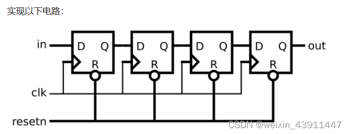
module top_module (
	input clk,
	input resetn,
	input in,
	output out
);

	reg [3:0] sr;

	// Create a shift register named sr. It shifts in "in".
	always @(posedge clk) begin
		if (~resetn)		// Synchronous active-low reset
			sr <= 0;
		else
			sr <= {sr[2:0], in};
	end

	assign out = sr[3];		// Output the final bit (sr[3])

endmodule
module top_module (
input clk,
input resetn, // synchronous reset
input in,
output out);
reg [2:0] q;
always@(posedge clk)
begin
if(!resetn)
{out,q}<=4'b0;
else
{out,q[2:0]}<={q[2:0],in};
end
endmodule
8. Shift register
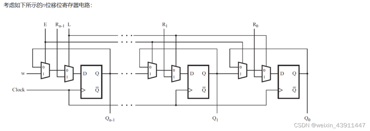
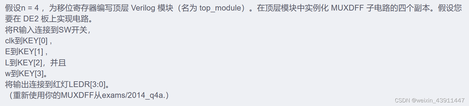
module top_module (
    input [3:0] SW,      //R
    input [3:0] KEY,     //0-clk,1-E,2-L,3-w
    output [3:0] LEDR    //out
); //
    MUXDFF u_3(SW[3],KEY[0],KEY[1],KEY[2],KEY[3],LEDR[3]);
    MUXDFF u_2(SW[2],KEY[0],KEY[1],KEY[2],LEDR[3],LEDR[2]);
    MUXDFF u_1(SW[1],KEY[0],KEY[1],KEY[2],LEDR[2],LEDR[1]);
    MUXDFF u_0(SW[0],KEY[0],KEY[1],KEY[2],LEDR[1],LEDR[0]);


endmodule

module MUXDFF (
    input R,
    input clk,
    input E,
    input L,
    input w,
    output q
);
    reg w1,d;
    always@(posedge clk)
        begin
           w1 = E?w:q;
            d = L?R:w1;
            q<=d;
        end
endmodule
9. 3-input LUT
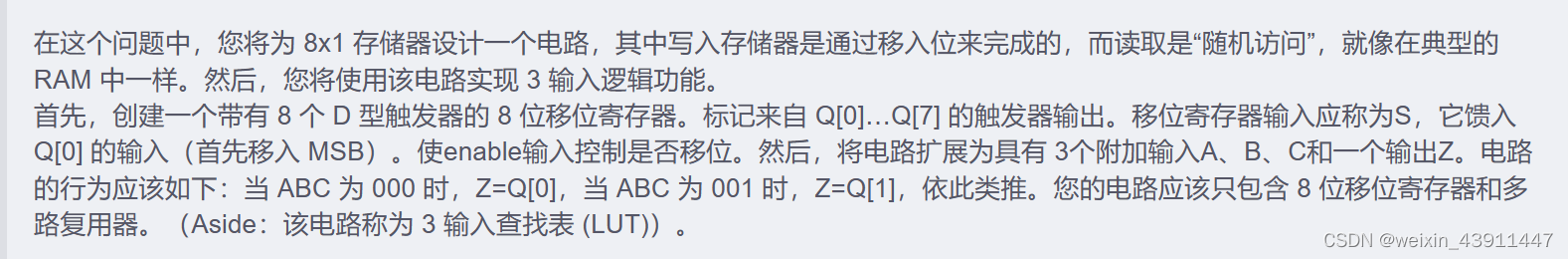
module top_module (
    input clk,
    input enable,
    input S,
    input A, B, C,
    output Z );
    reg [7:0] q;
    always@(posedge clk)
        begin
            if(enable)
                q<={q[6:0],S};
            else
                q<=q;
        end
    always@(*)
        begin
            case({A,B,C})
                3'b0:Z=q[0];
                3'b001:Z=q[1];
                3'b010:Z=q[2];
                3'b011:Z=q[3];
                3'b100:Z=q[4];
                3'b101:Z=q[5];
                3'b110:Z=q[6];
                3'b111:Z=q[7];
            endcase
        end
endmodule
module top_module (
	input clk,
	input enable,
	input S,

	input A, B, C,
	output reg Z
);

	reg [7:0] q;

	// The final circuit is a shift register attached to a 8-to-1 mux.


	// Create a 8-to-1 mux that chooses one of the bits of q based on the three-bit number {A,B,C}:
	// There are many other ways you could write a 8-to-1 mux
	// (e.g., combinational always block -> case statement with 8 cases).
	assign Z = q[ {A, B, C} ];


	// Edge-triggered always block: This is a standard shift register (named q) with enable.
	// When enabled, shift to the left by 1 (discarding q[7] and and shifting in S).
	always @(posedge clk) begin
		if (enable)
			q <= {q[6:0], S};
	end


endmodule


 8498
8498


 被折叠的 条评论
为什么被折叠?
被折叠的 条评论
为什么被折叠?
 到【灌水乐园】发言


