


Compute Shaders
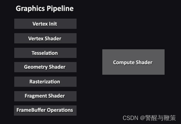
I’ve recently found myself (once again) obsessing over the GPU. Specifically, the piece of functionality that modern GPUs have: programmable shaders. The goal of the GPU is to take in data from the CPU – namely data regarding say, a mesh – then run that data through various stages of what’s known as the Graphics Pipeline to ultimately output colors onto your display. Prior to the programmable shader, this pipeline was fixed; meaning developers were quite limited in their ability to fine tune images displayed to their users. While today we’ve been graced by the programmable shaders, there are still pieces of the pipeline that remain fixed. This is actually a good thing. Functionality like primitive assembly, rasterization and per-sample operations are better left to the hardware. If you’ve ever done any graphics programming, you’ve probably seen a diagram that looks like this:
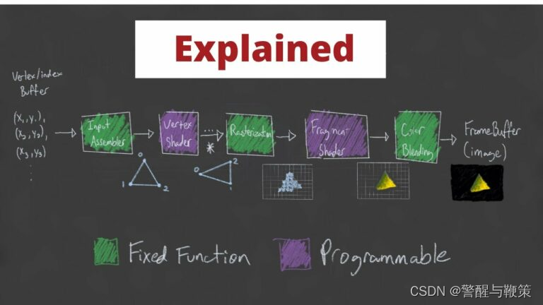 The boxes in green are fixed-function, whereas the purple boxes are programmable. There are actually far more stages than this, but for the most part, these are the stages we’re interested in. And just to be clear, pipeline is a really good name for this as each stage of this process is dependent on the stages prior. The Input Assembly stage is dependent on data being sent to the GPU via the CPU. The Vertex Shader stage is dependent on the input assembler’s triangle/primitive generation so that it can perform any transformations on the vertices that make up each primitive or even perform per-vertex lighting operations. The Rasterization stage needs to figure out what pixels on the screen map to the specified primitives/shapes so data relating to points on the primitives can be interpolated across the primitive, figuring out which of these points are actually within the Camera’s view, calculating depth for perspective cameras and ultimately mapping 3D coordinates to a 2D point on the screen. This leads to the Fragment Shader stage which deals with the fragments generated by the Rasterization Stage; specifically, how each of these pixels should be colored. The final Color Blending stage is responsible for performing any “last-minute” processing on all of the visible pixels using per-pixel shading data from the previous stage, any information that’s context specific to the pipeline state, the current contents of the render target and the contents of the depth and stencil buffers. This final stage also performs depth-testing. This just means that any pixels that are determined to be “behind” another pixel, in other words, will never be seen, will actually be removed when blending occurs. Long story long, the pipeline performs quite a few tasks that are happening unbelievably fast using the power of many, many shader cores and hardware designed to handle these very specific inputs and generate these very specific outputs.
Now, onto our good friend the Compute Shader who doesn’t really belong in the pipeline. As we’ve already seen, the pipelines job is to take data and turn it into colors on your screen. This is all leveraged by the fact that the processors responsible for these operations run in parallel, executing the same (hopefully) operations for every single pixel on the screen. This needs to be fast, especially given the increase in screen resolutions over the past decade. A 4K monitor, 3840 x 2160 pixels, has 8,294,000 pixels! Adding on to this insanity, some of the newer 4K monitors boast a 144Hz refresh rate with a 1ms response time! That’s a lot of work for our GPU to perform! Fortunately, it’s been crafted specifically for this duty. But what if we wanted to use this super-duper parallel computing for other purposes outside of the traditional render-pipeline? Because at the end of the day, the GPU and it’s tons of processors are generally just doing some simple math.
So, if we want to leverage the GPUs parallel processing talents outside of sending a buffer of colors to your monitor, we can use Compute Shaders. Directly from Microsoft, ” A compute shader provides high-speed general purpose computing and takes advantage of the large numbers of parallel processors on the graphics processing unit (GPU). The compute shader provides memory sharing and thread synchronization features to allow more effective parallel programming methods.” What this means is that we can parallelize operations that would otherwise be impractical to run via the CPU (without some of it’s own multi-processing capabilities).
So what might benefit from the use of Compute Shader? Well, some of the more common uses are related to image processing. If you think about the architecture of the GPU as a big grid containing tons of processors, you can think about mapping these processors via their location in the grid. For example, lets say I have a 512 x 512 pixel image where I want to invert every pixel of the original texture and store those inverted values into a new texture. Fortunately, this is a pretty trivial task for a compute shader.
In Unity, the setup code on the CPU looks something like this:
using UnityEngine;

public class ComputeInvertTest : MonoBehaviour
{
    // We want 16 threads per group.
    private const int ThreadsPerGroup = 16;

    // The compute shader.
    [SerializeField] private ComputeShader _testInverter;

    // The texture we want to invert.
    [SerializeField] private Texture2D _sourceTexture;

    // The mesh renderer that we want to apply the inverted texture to.
    [SerializeField] private MeshRenderer _targetMeshRenderer;

    // The texture we're going to store the inverted values for.
    private RenderTexture _writeTexture;

    private void Start()
    {
        // Create the destination texture using the source textures dimensions.
        // Ensure enableRandomWrite is set so we can write to this texture.
        _writeTexture = new RenderTexture(_sourceTexture.width, _sourceTexture.height, 1) {enableRandomWrite = true};

        // Get the resolution of the main texture - in our case, 512 x 512.
        var resolution = new Vector2Int(_sourceTexture.width, _sourceTexture.height);

        // We need to tell the compute shader how many thread groups we want.
        // A good rule of thumb is to figure out how many threads we want per group, then divide
        // the target dimensions by this number.
        // In our case, for our 512 x 512 texture, we want 16 threads per group.
        // This gives us 512 / 16, 512 / 16, or 32 thread groups on both the x and y dimensions.
        var numThreadGroups = resolution / ThreadsPerGroup;

        // Let's find the kernel, or the function, responsible for doing work in the compute shader.
        var inverterKernel = _testInverter.FindKernel("Inverter");

        // Set the texture properties for the source texture and destination textures.
        _testInverter.SetTexture(inverterKernel, Shader.PropertyToID("_WriteTexture"), _writeTexture, 0);
        _testInverter.SetTexture(inverterKernel, Shader.PropertyToID("_ReadTexture"), _sourceTexture, 0);

        // The Dispatch function executes the compute shader using the specified number of thread groups.
        _testInverter.Dispatch(inverterKernel, numThreadGroups.x, numThreadGroups.y, 1);

        // Finally, after the texture has been updated, apply it to the Meshrenderers material.
        _targetMeshRenderer.material.mainTexture = _writeTexture;
    }
}
On the GPU, the code is much simpler.
#pragma kernel Inverter
// The name of the kernel the CPU will look for.
#pragma kernel Inverter

// The number of threads we want per work group - this needs to match what we decided on the CPU side.
static int ThreadsPerGroup = 16;

// The texture we're reading from - no writing allowed here.
Texture2D<float4> _ReadTexture;
// The texture we're writing to, declared as RWTexture2D, or Read/Write Texture2D.
// The <float4> just says that each element in this texture is a 4 component vector, each
// component of type float.
RWTexture2D<float4> _WriteTexture;

// Again, specify the number of threads we want to set per thread group.
[numthreads(ThreadsPerGroup, ThreadsPerGroup, 1)]
void Inverter (uint3 id : SV_DispatchThreadID)
{
    // Write the inverted value to the destination texture.
    _WriteTexture[id.xy] = 1 - _ReadTexture[id.xy];
}
The important bit to realize here is that the attribute above the kernel, [ThreadsPerGroup, ThreadsPerGroup, 1], needs to match the number of threads we set on the CPU side. This value needs to be set at compile time, meaning it can’t change when the program is running. You may also notice this peculiar statement: uint3 id : SV_DispatchThreadID. This is where the magic happens – mapping our threads to our textures. Let’s break down the simple math.
We have a 512 x 512 texture. We want 16 threads per thread-group (or work-group) on both the x and y axes (because our texture is 2D – if our texture was 3D, it would likely be easier to specify 16 on all three axes ) and 1 on the z (we have to have at least 1 thread per group). This SV_DispatchThreadID maps to the following:
SV_GroupID * ThreadsPerGroup + SV_GroupThreadID = SV_DispatchThreadID
This looks like nonsense, I know. The best way to visualize this mapping is, again, like a grid. Taken from Microsoft’s website describing this exact calculation:
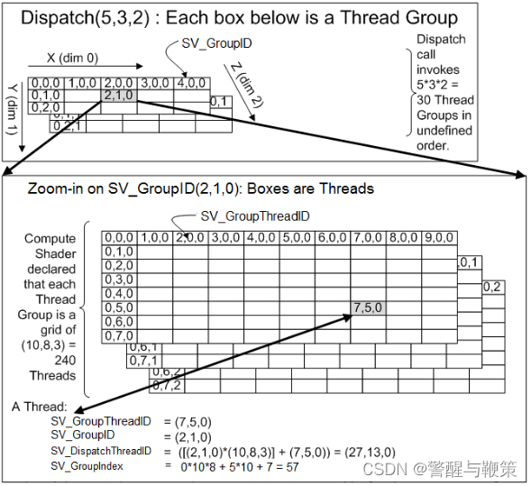 To relate this to our example, let’s remember that our Dispatch call invoked 32 x 32 x 1 Thread groups in an undefined order. So we can think of a 32 x 32 x 1 grid. Each cell of this grid corresponds to another grid – this time mapping to our 16 x 16 x 1 threads per group. This means, if a particular thread has been assigned to say, SV_GroupID of (31, 31, 0), or the last group (as these groups are zero indexed), and it happens to have an SV_GroupdThreadID of (15, 15, 1), or the last thread of this last group, we can calculate it’s 3D id, SV_DispatchThreadID. Doing the math:
SV_GroupID * ThreadsPerGroup + SV_GroupThreadID = SV_DispatchThreadID
(31, 31, 0) * (16, 16, 1) + (15, 15, 1) = (511, 511, 0).
Coincidentally, this is the address, or index, of the last pixel of the texture we’re reading from and writing to! So this mapping worked perfectly. There are a ton of tricks that can be done with playing with threads per group and work group counts, but for this case, it’s pretty straight forward. This is the result:
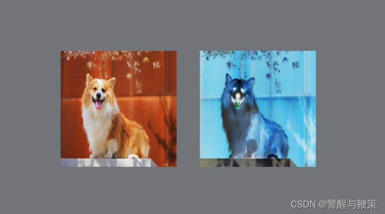 While this is a pretty contrived example, benchmarking this yielded a grand total of 1ms to invert this 512 x 512 image on the GPU. Just for some perspective, this exact same operation on the CPU took 117ms.
Going even further, using a 4k image, 4096 x 4096 pixels, this is the result:
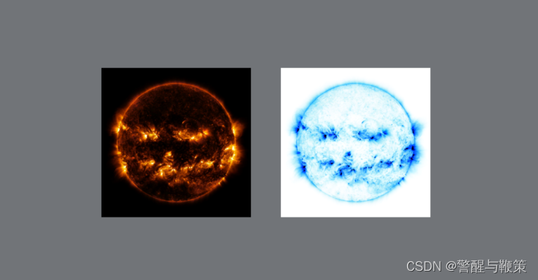 On the CPU, the inversion took 2,026ms, or just over 2 seconds. On the GPU, the inversion took, once again, 1ms. This is a staggering increase in performance! And just to provide a bit of machine specific information, I have an NVIDIA GeForce GTX 1080 GPU and an Intel Core i7-8700k CPU @ 3.70GHz.
///
GPU Computing
GPU computing has become increasingly popular in recent years due to the ability of modern graphics processing units (GPUs) to perform complex calculations in parallel, which makes them well-suited for a wide range of applications. Here are some examples of GPU computing applications:
- Scientific simulations: GPUs are commonly used for scientific simulations, such as climate modeling, astrophysics, and molecular dynamics. These simulations require vast amounts of data to be processed, which can be done efficiently using the parallel processing power of GPUs
- Machine learning: Machine learning algorithms often require the processing of large amounts of data, which can be done more efficiently using GPUs. GPUs can accelerate tasks such as training neural networks, which is a fundamental component of many machine learning applications.
- Video processing: GPUs can be used to accelerate video processing tasks, such as video encoding, decoding, and transcoding. This allows for faster rendering times and better quality output.
- Gaming: GPUs have long been used for gaming applications, as they can render high-quality graphics and provide smooth performance. However, GPUs can also be used for non-graphics tasks in games, such as physics simulations and artificial intelligence.
In recent times, the number of GPU computing applications has surged, and the list of available solutions continues to expand. Among the most widely used frameworks in this domain are CUDA, OpenCL, DirectCompute, and Metal.
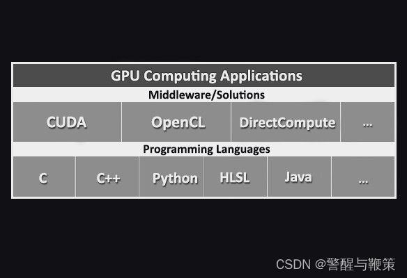
These frameworks enable developers to write code that can execute on GPUs, taking advantage of the massive parallelism offered by GPU architectures. They allow for efficient utilization of GPU resources, enabling computations to be performed in parallel across numerous processing cores.
Compute Shaders
First introduced by NVIDIA in 2006, compute shaders are a type of shader program that run on the graphics processing unit (GPU) and are designed to perform general-purpose computing tasks. Unlike traditional graphics shaders, which are used to render images, compute shaders can be used for a wide range of tasks. It is worth noting that they are not included by default in the Graphics Pipeline (even they are using GPU Hardware).
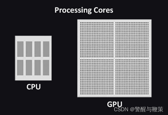
What makes compute shaders so powerful is their ability to harness the parallel processing power of modern graphics cards. With hundreds or even thousands of processing cores, a graphics card can perform computations that would take a traditional CPU-based program hours or even days to complete.
Because modern graphics cards have many processing cores, compute shaders can take advantage of this parallelism to perform computations much faster than traditional CPU-based programs. This makes them useful for a wide range of applications, from scientific simulations to video games.
So, the primary distinction between CPU and GPU architecture lies in their design objectives. CPUs are optimized for swift execution of a diverse range of tasks, typically measured by clock speed, but they have limitations in terms of concurrent task processing. On the other hand, GPUs are specifically engineered for concurrency.
Compute Shaders implementation in Unity
Compute shaders in Unity are closely aligned with the DirectX11 DirectCompute technology. The language used - HLSL.
They are compatible with a variety of platforms
- Windows and Windows Store (with a DirectX 11 or DirectX 12 graphics API and Shader Model 5.0 GPU)
- macOS and iOS (using Metal graphics API)
- Android
- Linux, and Windows platforms with Vulkan API, OpenGL platforms (OpenGL 4.3 on Linux or Windows; OpenGL ES 3.1 on Android).
- Modern game consoles.
In essence, Unity transforms the application code into platform-specific code that can be interpreted by the appropriate graphics API, depending on the target platform.
First Compute Shader
As this is the first article in a series, there is a high-level overview provided rather than delving into intricate technical details. Our focus will be on understanding the fundamentals of creating and utilizing compute shaders within Unity.
First, make sure that your system supports computes. In Unity, this information can be provided by SystemInfo.supportsComputeShaders.
In this sample, I've created a simple UI structure to visualize computes support.
Create a new C# script (named CheckComputeSupport in my case) and add it as a new component to any gameObject that is currently present on Scene (gameObject named CheckSupport in my case).
Script to check if Computes supported:
public class CheckComputeSupport : MonoBehaviour
{
    [SerializeField] private TMP_Text text;
    private void Start()
    {
        if(text != null)
            text.text = "Support Compute: " + SystemInfo.supportsComputeShaders;
    }
}
As you turn on the Play mode, it will produce such result:

If it's true, we can move on and create our first implementation of compute shaders.
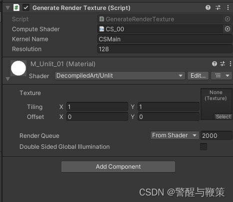
Create new compute shader (named CS_00 in my case) and C# (named GenerateRenderTexture in my case) script to Dispatch it.
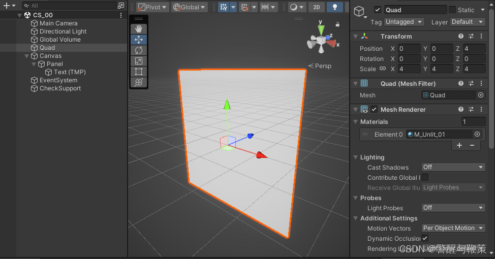
Also, add new Quad gameObject and set an Unlit material to it. For this, I've created a new default Unlit shader and set it to be used by M_Unlit_01 material.
Next, open newly created C# script and paste this code:
using UnityEngine;

namespace CS_00
{
    [RequireComponent(typeof(Renderer))]
    public class GenerateRenderTexture : MonoBehaviour
    {
        [SerializeField] private ComputeShader computeShader;
        [SerializeField] private string kernelName = "CSMain";
        [SerializeField] private int resolution = 128;

        private RenderTexture _renderTexture;
        private int _kernelHandle;

        private Renderer _renderer;
        private static readonly int MainTex = Shader.PropertyToID("_MainTex");

        private void Start()
        {
            //GET RENDERER COMPONENT REFERENCE
            TryGetComponent(out _renderer);

            //CREATE NEW RENDER TEXTURE TO RENDER DATA TO
            _renderTexture = new RenderTexture(resolution, resolution, 0)
            {
                enableRandomWrite = true
            };
            _renderTexture.Create();

            //COMPUTE SHADER & RESULTING RENDERTEXTURE SETUP
            _kernelHandle = computeShader.FindKernel(kernelName);
            computeShader.SetTexture(_kernelHandle, "Result", _renderTexture);
            _renderer.sharedMaterial.SetTexture(MainTex, _renderTexture);

            computeShader.Dispatch(_kernelHandle, resolution/8, resolution/8, 1);
        }
        private void OnDisable()
        {
            if (_renderTexture != null)
                Destroy(_renderTexture);

            _renderer.sharedMaterial.SetTexture(MainTex, null);
        }
    }
}
For Compute shader, use this code:
#pragma kernel CSMain

RWTexture2D<float4> Result;

[numthreads(8,8,1)]
void CSMain (uint3 id : SV_DispatchThreadID)
{
    Result[id.xy] = float4(id.x & id.y, (id.x & 15)/15.0, (id.y & 15)/15.0, 0.0);
}
No worries, in upcoming articles we will break down the code used for compute shader, as well as contained within C# script.
Add GenerateRenderTexture component to the Quad gameObject (AddComponent -> GenerateRenderTexture). It will add a new component with default values set.
Turn on PlayMode and check the result, that should be somewhere similar to this:
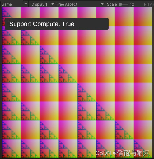
Congratulations on successfully setting up and running your initial compute shader. As previously mentioned, in the upcoming article, we will delve into the technical intricacies and fundamental structural components that a compute shader is consists of.
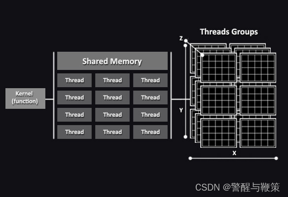
Compute Shader Core Elements: Kernel, Thread, Group
Before explaining the particular implementation, it is necessary to explain compute shader's core elements and concepts behind their functionality.
For each shader, building block are: Kernel, Thread, Group.
A Kernel is the entry point (treated as a function as well) in the compute shader code that gets executed on the GPU. It defines the operations and computations to be performed on the data. Each kernel can be thought of as an independent task that is executed in parallel.
A Thread represents an individual unit of execution within a kernel. Threads are the smallest unit of work in a compute shader. Multiple threads are created and executed concurrently to process data in parallel. Each thread typically operates on a unique set of data or performs a specific computation. One thread executes one kernel. Probably, one of the remarkable advantages of compute shaders is their ability to execute kernels concurrently across multiple threads. Speaking of concurrency...
Concurrency is an ability of a system or program to execute multiple tasks or operations simultaneously. In a concurrent system, different tasks can be executed independently and progress concurrently, potentially overlapping in time. More on Concurrency.
Thread itself is specified in three dimensions (X, Y, Z). As an example (from previous article), [numthreads(8,8,1)] will run 8*8*1 = 64 threads simultaneously. If [numthreads(32,2,1)] then 32*2*1 = 64 threads will run concurrently. While the total number of threads remains constant, there are scenarios where it is more advantageous to specify the threads in two dimensions, such as (8, 8, 1). We will delve into these details later.
Finally, a Group is a unit for threads execution. Threads, executed by a group, are called Threads Group. It's a collection of threads that are grouped together for synchronization and communications purposes. Threads group can share data and coordinate their operations. Group size is defined by the developer and depends on the specific requirements of the computation being performed.
First Compute Shader setup review
Now, as you're familiar with compute shaders' core elements, it's a good point to break down the C# script and compute shader code from the previous article.
Compute shader (named CS_00) code:
#pragma kernel CSMain

RWTexture2D<float4> Result;

[numthreads(8,8,1)]
void CSMain (uint3 id : SV_DispatchThreadID)
{
    Result[id.xy] = float4(id.x & id.y, (id.x & 15)/15.0, (id.y & 15)/15.0, 0.0);
}
Kernel creation
#pragma kernel CSMain
Compute kernel function creation with #pragma directive. By default, the kernel function is named CSMain, but you have the flexibility to assign your preferred name. It is mandatory to have at least one kernel that can be invoked (dispatched) from any script (C#) using the Dispatch() method.
Texture2D with Read/Write enabled flag
RWTexture2D<float4> Result;
Texture2D creation. Float4 stands for R, G, B, A channels respectively. The "RW" prefix signifies that this texture is used for both reading from and writing to. It's required as we're making per-pixel calculations and storing results within this texture.
Numthreads
[numthreads(8,8,1)]
As mentioned earlier, threads groups in compute shaders are specified within multidimensional array. Each threads group comprises multiple threads, which are also operating in three dimensions. The numthreads statement informs the compute shader about the number of threads present in each dimension of a thread group. In this specific scenario, threads array represented as 8x8x1.
A common question that arises is, "Why specify the third coordinate if only two coordinates are used?". The answer lies in the fact that the total number of threads is determined by the multiplication of all three coordinate values. If the third value is set to 0, the overall product would also be 0. For instance, let's consider the coordinates (4, 2, 0), where 4 * 2 * 0 equals 0.
Since our goal is to populate pixels with values from the compute shader, it becomes remarkably simple to visualize the process of creating thread groups and comprehend the logic behind it.
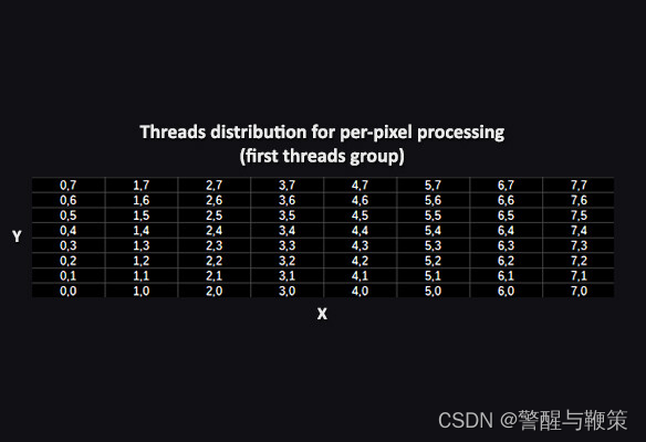
In order to threads group be created, we use specified earlier numbers of threads for X, Y and Z coordinates respectfully. So, 8*8*1 = 64, which means that one threads group would handle 8 by 8 pixels area. The first threads group will have and ID (0,0,0).
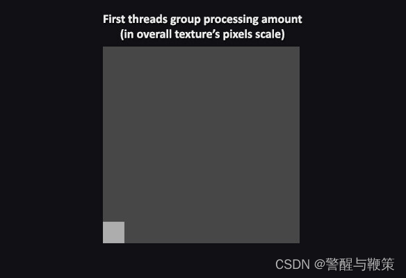
Next one (shifted by X) - (1,0,0), etc.
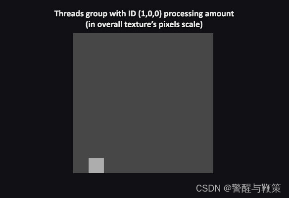
So, the total number of threads groups that are required to process the total amount of Texture's pixels will be equal to texResolution/8.
Kernel function
void CSMain (uint3 id : SV_DispatchThreadID)
{
    Result[id.xy] = float4(id.x & id.y, (id.x & 15)/15.0, (id.y & 15)/15.0, 0.0);
}
In order to execute a kernel, it is necessary to provide a parameter id of type uint3 (a three-component vector) with the SV_DispatchThreadID semantic.
Semantics is a set of compute shader's instructions that specifies a series of actions the compiler needs to perform with the provided parameter "id" (uint3). Semantics are used between different stages of the shader processing pipeline.
More on SV_DispatchThreadID semantic you can discover here.
Kernel (function) body:
Result[id.xy] = float4(id.x & id.y, (id.x & 15)/15.0, (id.y & 15)/15.0, 0.0);
Don't be too confused on that particular equation. It's a fractal, created by polish mathematician Wacław Sierpiński. You can learn more about it here.
For now, it's far more important to understand how the value of Result[id.xy] is formed, which is done using the float4() constructor. The float4<> structure comprises four values: R, G, B, and A. These values represent the red, green, blue, and alpha channels, respectively.
At this point, we're finished with compute shader's code breakdown. Let's take a closer look at relative C# script.
C# script (named GenerateRenderTexture) code:
using UnityEngine;

namespace CS_00
{
    [RequireComponent(typeof(Renderer))]
    public class GenerateRenderTexture : MonoBehaviour
    {
        [SerializeField] private ComputeShader computeShader;
        [SerializeField] private string kernelName = "CSMain";
        [SerializeField] private int resolution = 128;

        private RenderTexture _renderTexture;
        private int _kernelHandle;

        private Renderer _renderer;
        private static readonly int MainTex = Shader.PropertyToID("_MainTex");

        private void Start()
        {
            //GET RENDERER COMPONENT REFERENCE
            TryGetComponent(out _renderer);

            //CREATE NEW RENDER TEXTURE TO RENDER DATA TO
            _renderTexture = new RenderTexture(resolution, resolution, 0)
            {
                enableRandomWrite = true
            };
            _renderTexture.Create();

            //COMPUTE SHADER & RESULTING RENDERTEXTURE SETUP
            _kernelHandle = computeShader.FindKernel(kernelName);
            computeShader.SetTexture(_kernelHandle, "Result", _renderTexture);
            _renderer.sharedMaterial.SetTexture(MainTex, _renderTexture);

            computeShader.Dispatch(_kernelHandle, resolution/8, resolution/8, 1);
        }
        //TO MAKE SURE THAT GENERATED RENDERTEXTURE IS DISPOSED/CLEARED
        private void OnDisable()
        {
           if (_renderTexture != null)
               Destroy(_renderTexture);

           _renderer.sharedMaterial.SetTexture(MainTex, null);
        }
    }
}
To enhance code understanding, you will find that logical blocks are commented throughout. Now, let's direct our attention to the specific parts that are relevant to the logic of the compute shader processing.
Kernel handle:
_kernelHandle = computeShader.FindKernel(kernelName);
Used to find the index of the compute shader kernel. Since a single compute shader can have multiple kernels (we will talk about that in upcoming articles), the FindKernel() method is employed to retrieve the kernel index based on the provided kernel name.
Set Compute Shader texture parameter:
computeShader.SetTexture(_kernelHandle, "Result", _renderTexture);
SetTexture() function can set a texture for reading in the compute shader or for writing into as an output.
Set MeshRenderer's material texture property:
_renderer.sharedMaterial.SetTexture(MainTex, _renderTexture);
Launch/Execute/Dispatch Compute Shader:
computeShader.Dispatch(_kernelHandle, resolution/8, resolution/8, 1);
Dispatch() function executes the compute shader by launching a specific number of compute shaders threads groups in the X, Y, and Z dimensions. As was mentioned earlier, denominator equals value of threads on X and Y coordinates.
For the sake of experimentation and curiosity, you can manipulate the value of the denominator and observe the resulting effects. (Spoiler) As the denominator increases, fewer pixels of the texture will receive calculated data. Feel free to try it out and enjoy the process!
Multiple Kernels
In compute shaders, multiple kernels can be used to perform different computations or operations within a single compute shader program. To work with multiple kernels in a compute shader, each kernel should be defined as a separate function. Each kernel can have its own set of input and output variables, and it can perform specific computations or operations based on its defined functionality.
Using multiple kernels in compute shaders can be beneficial in scenarios where complex computations or different stages of a computation need to be performed in parallel, allowing for efficient GPU utilization and accelerated processing of large datasets.
Now, let's take a loot at a practical example of multiple kernels' usage.
Multiple Kernels (Texture-based example)
we had a glimpse of what it's look like to work with textures generation and per-pixel calculation through compute shader processing. This time, we'll populate pixel data with values, that are calculated with multiple kernels' usage.
To start off, prepare some basic setup to visualize compute shader's output results.
Create a quad gameObject with assigned default Unlit material.
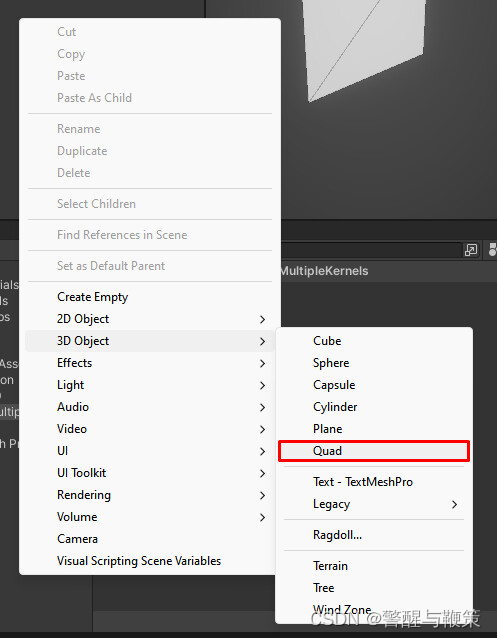
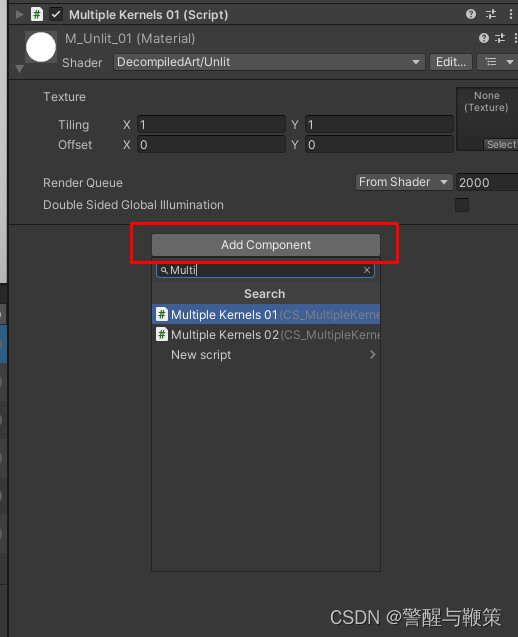
To get started, create a new .compute shader asset and a new C# script. Copy/paste the following code into the respective files and add C# script as a new component for a newly added quad gameObject.
Now we can proceed with reviewing of .compute & C# script usage.
Compute shader (named CS_MultipleKernels_01) code:
#pragma kernel TintBlue
#pragma kernel TintYellow

RWTexture2D<float4> Result;

uniform float4 tint01;
uniform float4 tint02;

[numthreads(8,8,1)]
void TintBlue (uint3 id : SV_DispatchThreadID)
{
    Result[id.xy] = tint01;
}

[numthreads(8,8,1)]
void TintYellow (uint3 id : SV_DispatchThreadID)
{
    Result[id.xy] = tint02;
}
Color tint values
uniform float4 tint01;
uniform float4 tint02;
properties to store color (float4) data.
Kernels
[numthreads(8,8,1)]
void TintBlue (uint3 id : SV_DispatchThreadID)
{
    Result[id.xy] = tint01;
}

[numthreads(8,8,1)]
void TintYellow (uint3 id : SV_DispatchThreadID)
{
    Result[id.xy] = tint02;
}
Kernels generate per-pixel values based on the tint01 and tint02 parameters.
C# script (named MultipleKernels01) code
public class MultipleKernels01 : MonoBehaviour
{
    [SerializeField] private ComputeShader computeShader;
    [SerializeField] private KernelData[] kernelsData;
    [SerializeField] private int textureResolution = 128;

    private RenderTexture _renderTexture;
    private int[] _kernelsHandles;

    private Renderer _renderer;
    private static readonly int MainTex = Shader.PropertyToID("_MainTex");

    private void Start()
    {
        //GET RENDERER COMPONENT REFERENCE
        TryGetComponent(out _renderer);

        //CREATE NEW RENDER TEXTURE TO RENDER DATA TO
        _renderTexture = new RenderTexture(textureResolution, textureResolution, 0)
        {
            enableRandomWrite = true
        };
        _renderTexture.Create();

        if(kernelsData.Length < 1) return;

        _kernelsHandles = new int[kernelsData.Length];
        computeShader.SetInt("textureResolution", textureResolution);

        for (var i = 0; i < kernelsData.Length; i++)
        {
            var kernelName = kernelsData[i].name;

            _kernelsHandles[i] = computeShader.FindKernel(kernelName);

            computeShader.SetTexture(_kernelsHandles[i], "result", _renderTexture);
            computeShader.SetVector(kernelsData[i].shaderTintPropertyName, kernelsData[i].tint);

            computeShader.Dispatch(_kernelsHandles[i], textureResolution/kernelsData[i].dispatchDividers.x,
                textureResolution/kernelsData[i].dispatchDividers.y, 1);
        }

        _renderer.sharedMaterial.SetTexture(MainTex, _renderTexture);
    }

    private void OnDisable()
    {
        if (_renderTexture != null)
            Destroy(_renderTexture);

        _renderer.sharedMaterial.SetTexture(MainTex, null);
    }

    [Serializable]
    private struct KernelData
    {
        public string name;
        public string shaderTintPropertyName;
        public Color tint;
        public int2 dispatchDividers;
    }
}
Since we have already reviewed the majority of the C# script code let's focus on the distinctive aspects specific to this particular article.
Multiple kernels processing
for (var i = 0; i < kernelsData.Length; i++)
{
    var kernelName = kernelsData[i].name;

    //COMPUTE SHADER & RESULTING RENDERTEXTURE SETUP
    _kernelsHandles[i] = computeShader.FindKernel(kernelName);

    computeShader.SetTexture(_kernelsHandles[i], "result", _renderTexture);
    computeShader.SetVector(kernelsData[i].shaderTintPropertyName, kernelsData[i].tint);

    computeShader.Dispatch(_kernelsHandles[i], textureResolution/kernelsData[i].dispatchDividers.x,
        textureResolution/kernelsData[i].dispatchDividers.y, 1);
}
To simplify the process, a for loop is utilized to handle all kernels and their associated data (with SetTexture() and SetVector() methods). To determine which portion of the texture's pixels should be populated by the output of a specific kernel (RWTexture2D Result), you have the flexibility to specify a custom number of thread groups for each coordinate (X, Y, Z).
Coordinate X = textureResolution/kernelsData[i].dispatchDividers.x.
Coordinate Y = textureResolution/kernelsData[i].dispatchDividers.y.
Coordinate Z = 1.
Two coordinates values required to correctly process per-pixel data as texture itself is represents by X,Y coordinates (values for them are set with textureResolution). dispatchDividers are specified through KernelData.
KernelData struct
[Serializable]
private struct KernelData
{
    public string name;
    public string shaderTintPropertyName;
    public Color tint;
    public int2 dispatchDividers;
}
Struct is used to define different elements for configuring compute shader kernels. It needs to be serialized so that we can easily view and modify its values.
Let's test the result of texture's per-pixel processing.
By setting custom values for the dispatchDividers, we have the ability to control the number of pixels processed by a specific kernel. This allows us to adjust the amount of work performed by the kernel on a per-pixel basis.
With that, we have completed the first example showcasing the usage of multiple kernels for per-pixel processing of a texture. In the next example, we will delve into another component that requires examination: the Compute Buffer.
Compute Buffers
When working with compute shaders, Compute Buffers are a type of data structure that allow efficient data communication between the CPU and GPU. They serve as a bridge for transferring data, enabling parallel processing on the GPU, designed to store large amounts of structured data (such as arrays of elements or structs).
Compute Buffers have a defined size, which determines the maximum number of elements they can hold. Each element within the buffer has a specific stride, representing the size in bytes of that element. The stride is used to calculate memory offsets and determine the layout of the buffer's data.
These buffers are particularly useful for scenarios involving large-scale computations, simulations, or data processing tasks. They facilitate efficient data transfer and parallel processing, leveraging the computational power of the GPU to accelerate performance.
CPU-GPU data transfer with Compute Buffers
Multiple Kernels (Calculations-based example)
Now, as we've scratched the surface of what Compute Buffers are, we'll take a loot at how compute shaders could be used to process simple calculation with provided data.
The practical objective of this example is to transfer data from the CPU to the GPU, perform calculations, receive the results, and output them using Debug.Log() for logging purposes. During this process, RWStructuredBuffer type of Compute Buffer will be used.
RWStructuredBuffer is a type of read-write buffer that provides read and write access to structured data from within a compute shader kernel. This buffer can hold elements of a specific structure or data type. Each element in the buffer can contain multiple data fields, such as floats, integers, vectors, or custom data structures.
(Just like earlier) create a new .compute asset and related C# script. Follow the same process of adding a new component to existing quad gameObject.
Compute shader (named CS_MultipleKernels_02) code:
#pragma kernel Kernel01
#pragma kernel Kernel02

RWStructuredBuffer<int> intBuffer;
int intValue;

[numthreads(8,1,1)]
void Kernel01 (uint3 id : SV_DispatchThreadID)
{
    intBuffer[id.x] = id.x * intValue;
}

[numthreads(8,1,1)]
void Kernel02 (uint3 id : SV_DispatchThreadID)
{
    intBuffer[id.x] += 1;
}
Kernel01 set up
[numthreads(8,1,1)]
void Kernel01 (uint3 id : SV_DispatchThreadID)
{
    intBuffer[id.x] = id.x * intValue;
}
Kernel01 computes the multiplication result of id.x and intValue (which is set from the C# script).
Kernel02 set up
[numthreads(8,1,1)]
void Kernel02 (uint3 id : SV_DispatchThreadID)
{
    intBuffer[id.x] += 1;
}
Kernel01 computes the sum result of id.x and intValue (which is set from the C# script).
C# script (named MultipleKernels02) code
public class MultipleKernels02 : MonoBehaviour
{
    [SerializeField] private ComputeShader computeShader;
    [Range(1,8)][SerializeField] private int computeBufferSize = 4;
    [SerializeField] private int intValue;
    [SerializeField] private string kernel01Name;
    [SerializeField] private string kernel02Name;

    private int _kernelsHandle01;
    private int _kernelsHandle02;

    private ComputeBuffer _computeBuffer;

    private void Start()
    {
        if(!computeShader) return;

        #region PROCESS_KERNEL01
        //KERNELS SET UP
        _kernelsHandle01 = computeShader.FindKernel(kernel01Name);
        _kernelsHandle02 = computeShader.FindKernel(kernel02Name);

        //ARGUMENTS: SIZE OF THE AREA TO BE SAVED, SIZE PER UNIT OF DATA TO BE SAVED
        _computeBuffer = new ComputeBuffer(computeBufferSize, sizeof(int));

        computeShader.SetBuffer(_kernelsHandle01,"intBuffer", _computeBuffer);
        computeShader.SetInt("intValue", intValue);
        computeShader.Dispatch(_kernelsHandle01, 1,1,1);

        int[] result = new int[computeBufferSize];
        _computeBuffer.GetData(result);

        for (var i = 0; i < computeBufferSize; i++)
        {
            Debug.Log("Kernel01 Processing: " + result[i]);
        }

        #endregion

        #region PROCESS_KERNEL02

        computeShader.SetBuffer(_kernelsHandle02,"intBuffer", _computeBuffer);
        computeShader.Dispatch(_kernelsHandle02, 1,1,1);

        _computeBuffer.GetData(result);

        for (var i = 0; i < computeBufferSize; i++)
        {
            Debug.Log("Kernel02 Processing: " + result[i]);
        }

        #endregion
    }

    private void OnDestroy()
    {
        _computeBuffer.Release();
    }
}
Creating new ComputeBuffer
_computeBuffer = new ComputeBuffer(computeBufferSize, sizeof(int));
ComputeBuffer(int count, int stride) constructor is used to create a ComputeBuffer object, which serves as a buffer for storing data that can be accessed and manipulated by compute shaders.
• count specifies the number of elements or data points that the buffer can store. This value indicates the size of the buffer.
• stride represents the size in bytes of each individual element in the buffer. It determines the spacing between elements in the buffer and is used to calculate memory offsets.
Once you have created a ComputeBuffer, you can set and get data to and from it using various methods provided by the class, such as SetData() and GetData(). These methods allow you to transfer data between the CPU and GPU.
Passing ComputeBuffer to Compute Shader:
computeShader.SetBuffer(_kernelsHandle01,"intBuffer", _computeBuffer);
SetBuffer() method is used to bind a ComputeBuffer to a shader for use in a compute shader. It establishes a connection between a ComputeBuffer and a shader, allowing the shader to read from or write to the data stored in the ComputeBuffer.
Compute Shader Dispatch/Execute
computeShader.Dispatch(_kernelsHandle01, 1,1,1);
It's important to note that in this case, we are passing a single thread group for each value in the three-dimensional array (1 for X, Y, and Z, respectively). Since we are working with a simple data set that is involved in the calculations, we only need to specify a single threads group (X coordinate) for the computation.
We also specifying the max amount of output results by settings computeBufferSize. But output length can not exceed of maximum threads set within compute shader (currently set to numthreads(8,1,1)).
_computeBuffer = new ComputeBuffer(computeBufferSize, sizeof(int));
As a reminder, in order to calculate the total number of threads involved, we need to multiply the values of each thread group. Therefore, we assign a value of 1 to Y and Z by default, ensuring that the multiplication produces the correct output.
Get Compute Shader calculation results:
int[] result = new int[computeBufferSize];
_computeBuffer.GetData(result);
Get compute shader's calculation results with GetData() method and pass that data into an output array of integers (allocated earlier).
Clear ComputeBuffer
_computeBuffer.Release();
After using a ComputeBuffer, it's important to release its resources by calling the Release() method to avoid memory leaks.
Turn on Play mode and check console for expected compute shader's output.
Component fields' values and Log output result
Based on the specified computeBufferSize, you should obtain a corresponding number of output results. Congratulations! You've now succesfully processed data through CPU-GPU compute pipeline.
///


 2728
2728


 被折叠的 条评论
为什么被折叠?
被折叠的 条评论
为什么被折叠?
 到【灌水乐园】发言


