


💥💥💞💞欢迎来到本博客❤️❤️💥💥
🏆博主优势:🌞🌞🌞博客内容尽量做到思维缜密,逻辑清晰,为了方便读者。
⛳️座右铭:行百里者,半于九十。
📋📋📋本文目录如下:🎁🎁🎁
目录
💥1 概述
一种改进多旋翼无人机动态仿真的模块化仿真环境研究
多旋翼无人机(UAV)由于其多功能性和机械简单性而在研究和商业应用中都获得了极大的普及。然而,尽管有这些优势,多旋翼系统在设计保证安全可靠飞行性能的强大控制架构方面仍然是一个相当大的挑战。按照今天的惯例,制导、控制和导航算法(GNC)的设计主要在仿真中进行。为了保证在仿真环境中生成的控制解决方案与真实飞行性能之间的无缝转换,仿真应以足够的保真度再现真实世界的行为。
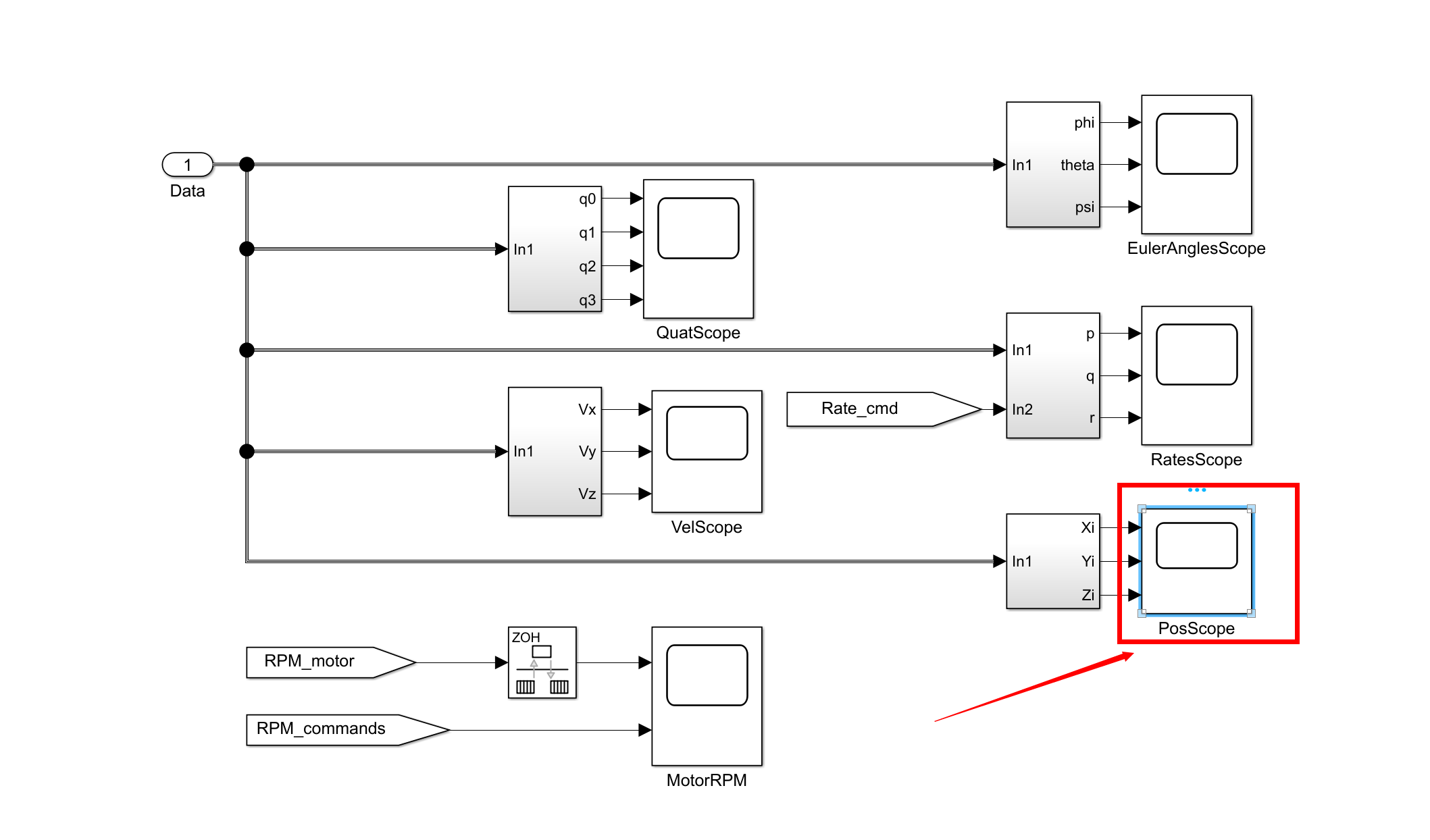
该仿真包括任意多旋翼无人机的改进动态模型。仿真非常模块化,允许用户指定几乎任何可以想象的多旋翼机身,无论对称性或特定布局如何。与在室外飞行真正的无人机相比,所包含的环境效果也有助于使模拟行为更自然。模拟包括随附论文文本中描述的所有场景。其中包括:任意非对称机身,改变机身质量或惯性矩或在飞行过程中引入执行器故障的能力,机身上的空气动力阻力,动态推力产生,不同的空气动力学螺旋桨模式,如涡环状态和叶片拍打效应。如果需要,用户可以关闭所有这些效果。
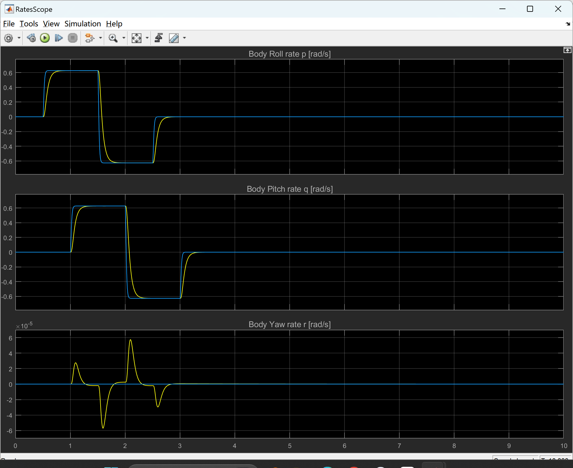
当前实现的控制器仅是内环角速率控制。由用户决定实施他们选择的更高级的控制方案。
1. 研究背景与意义
多旋翼无人机在复杂环境(如动态风场、移动平台着陆)中的仿真需求日益增加,但传统仿真工具在模型复杂性、环境适应性和实时性方面存在局限。模块化仿真环境通过解耦功能模块、标准化接口和动态模型优化,可显著提升仿真精度与效率,为控制算法开发、硬件在环测试和场景验证提供可靠支撑。
2. 现有仿真方法的不足
- 模型复杂性不足:传统工具(如Simulink/SimMechanics)依赖固定动力学模型,难以自定义机身参数(如非对称布局、质量分布),导致仿真与真实飞行偏差较大。
- 环境适应性局限:多数平台未集成复杂风场(如Dryden紊流模型)或动态障碍物,难以模拟无人机在近地效应、涡环状态下的行为。
- 实时性瓶颈:Matlab方程解算器在复杂模型下易出现延迟,影响硬件在环测试的同步性。
- 扩展性受限:非模块化设计导致传感器、执行器或控制算法替换困难,难以支持多机协同仿真。
3. 模块化仿真环境的设计原则
- 功能独立性:将系统拆分为动力学模型、环境交互、控制算法和可视化模块,每个模块可独立开发与测试。
- 接口标准化:采用统一数据格式(如JSON/XML)和通信协议(如ROS主题),确保模块间无缝集成。
- 可扩展性:支持用户自定义参数(如旋翼布局、惯性矩阵)和插件式添加新功能(如故障注入模块)。
- 实时性保障:通过分层调度机制分离高频率控制计算与低频率环境渲染,优化资源分配。
4. 关键改进技术
4.1 动态模型精细化
- 多旋翼参数化建模:支持机身对称性、电机性能(如KV值、扭矩曲线)和螺旋桨气动特性(如涡环状态、叶片拍打效应)的自定义配置,提升模型物理真实性。
- 环境交互增强:集成风场模型(Dryden紊流、地面效应反射模型)和障碍物动态响应,支持复杂场景下的飞行稳定性测试。
4.2 实时性优化
- 硬件加速:利用FPGA或GPU并行计算推力分配算法,缩短仿真步长时间至微秒级。
- 轻量化通信协议:采用UDP协议传输状态数据,减少ROS节点间的通信延迟。
4.3 故障注入与容错测试
- 执行器故障模拟:可设置电机停转、响应延迟或效率衰减,验证容错控制算法(如滑模容错控制器)的鲁棒性。
5. 现有开源/商用平台对比
| 平台 | 核心架构 | 优势 | 局限性 |
|---|---|---|---|
| XTDrone | ROS/Gazebo/PX4 | 支持多机协同、真实传感器模型(如双目SLAM) | 动态风场模型精度不足 |
| Simulink | 图形化模块化设计 | 快速原型开发、与硬件无缝对接 | 实时性差、扩展性有限 |
| AirSim | UE4引擎/物理引擎集成 | 高保真视觉渲染、支持强化学习训练 | 计算资源需求高、动力学简化 |
6. 模块化接口与数据交互协议
- 物理接口:遵循ISO 13628标准,定义电机驱动信号(PWM频率)、IMU数据帧结构和电源管理协议。
- 逻辑接口:
- 控制指令接口:采用MAVLink协议传输姿态指令(Roll/Pitch/Yaw)和位置目标。
- 状态反馈接口:通过ROS消息发布无人机位姿、电池状态和环境参数(风速、障碍物坐标)。
- 数据兼容性:支持与MATLAB/Simulink、Python(如PyBullet)和C++的跨平台数据交换,避免格式转换冗余。
7. 动态仿真验证方法
7.1 验证流程
- 功能验证:通过定向测试(如阶跃响应、轨迹跟踪)检验基础动力学模型。
- 边界条件测试:模拟极端场景(如最大负载、电机单点故障),评估控制算法鲁棒性。
- 随机扰动测试:注入高斯噪声和随机风场,验证环境适应性。
7.2 性能指标
- 跟踪精度:位置误差(RMSE)与姿态误差(欧拉角偏差)。
- 实时性:仿真步长与实际时间的比率(需≤1)。
- 计算资源占用率:CPU/GPU利用率与内存消耗,优化硬件配置。
8. 结论与未来方向
模块化仿真环境通过动态模型细化、接口标准化和实时性优化,显著提升了多旋翼无人机在复杂场景下的仿真可信度。未来研究方向包括:
- 智能算法集成:结合强化学习在线优化控制参数,实现仿真到现实(Sim2Real)的无缝迁移。
- 多物理场耦合:引入电磁干扰模型与多无人机气动相互作用,支持集群协同仿真。
- 量子计算加速:探索量子优化算法在轨迹规划中的应用,突破传统计算瓶颈。
通过持续迭代模块化设计与验证方法,该仿真环境有望成为无人机技术研发的核心工具,推动工业检测、灾害救援等领域的实用化进程。
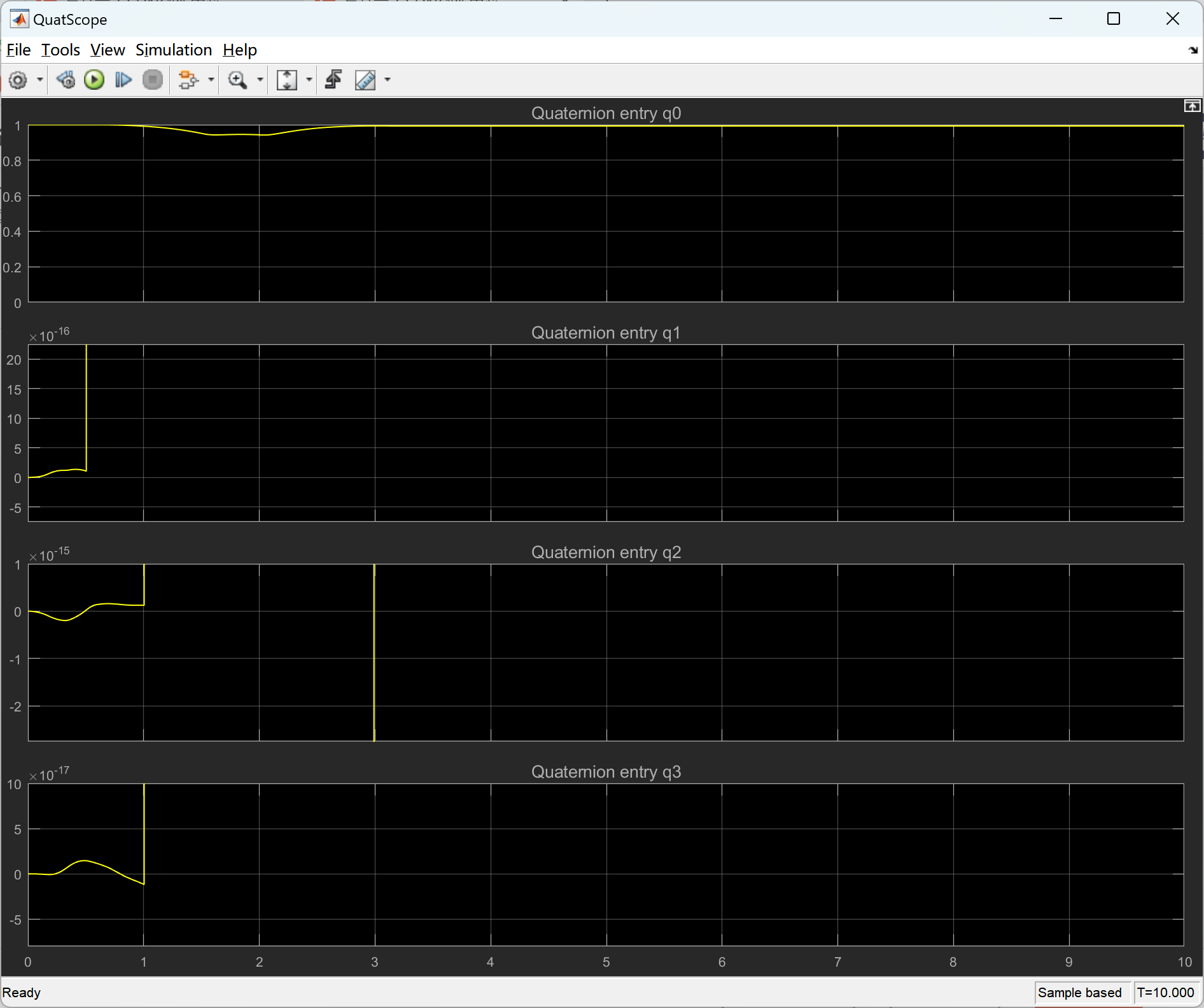
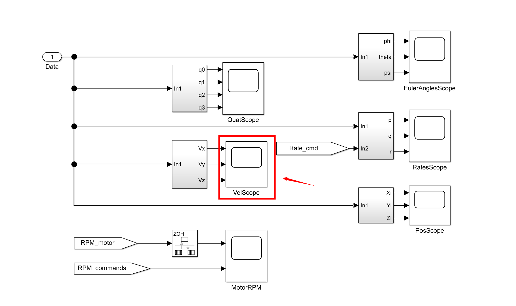
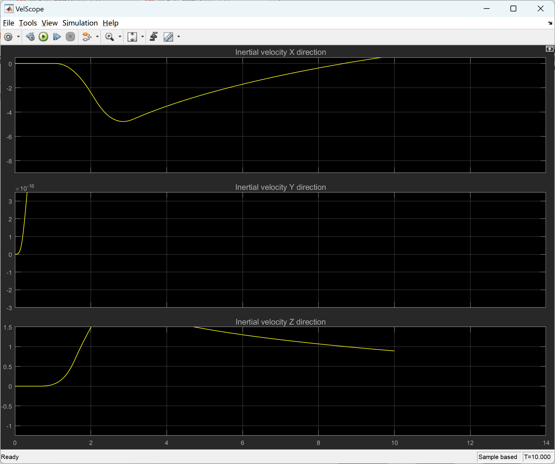
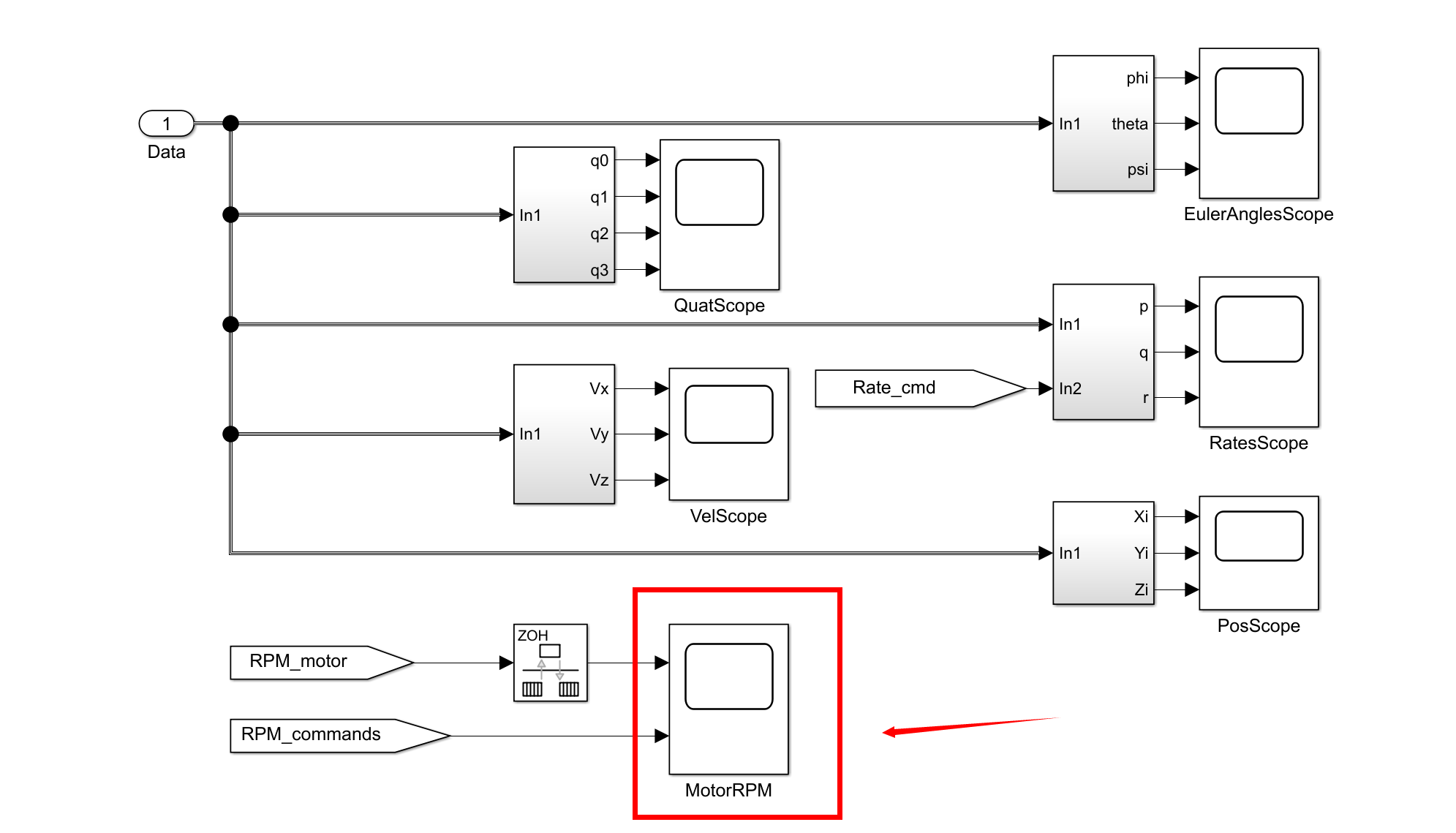
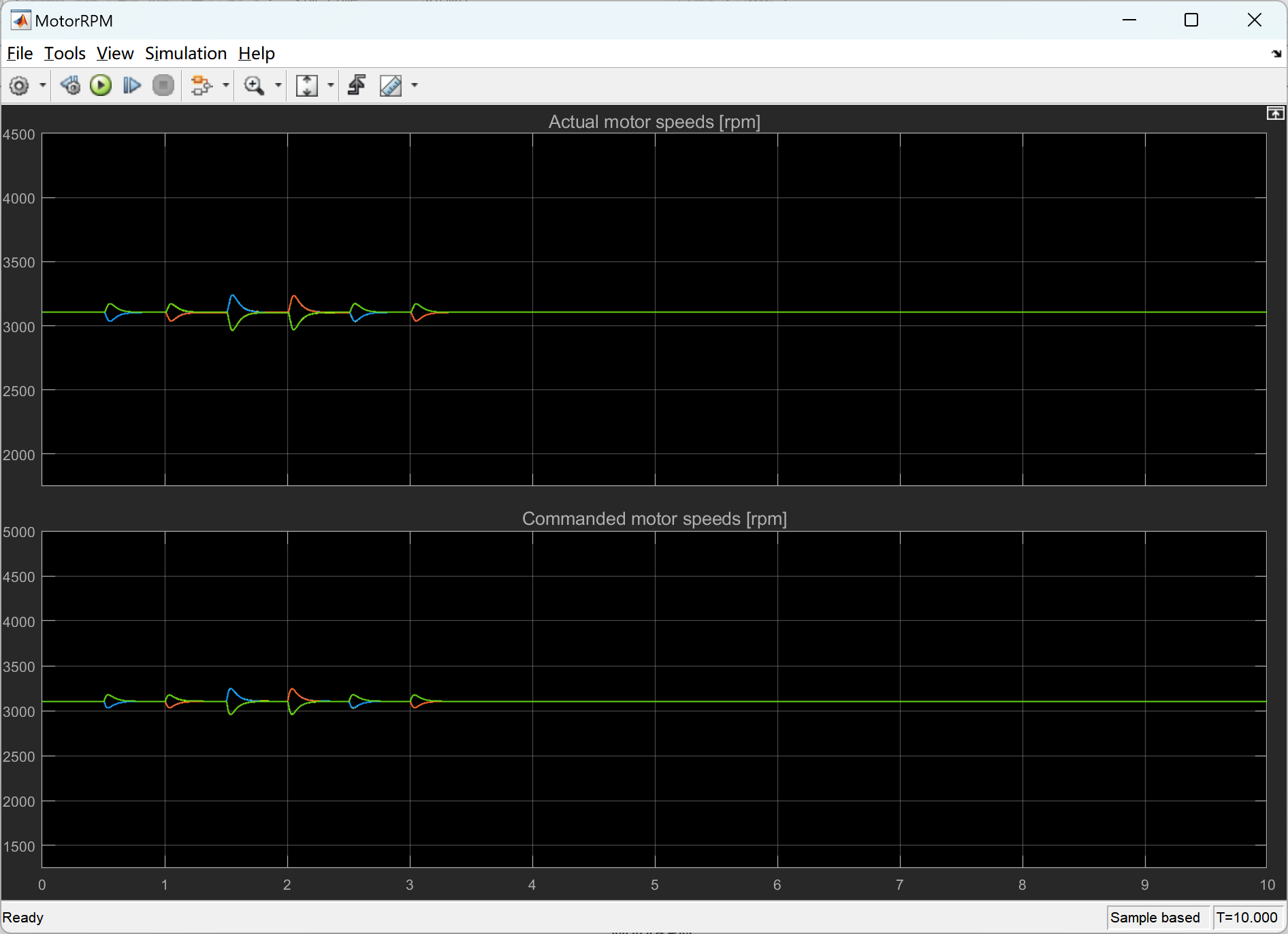
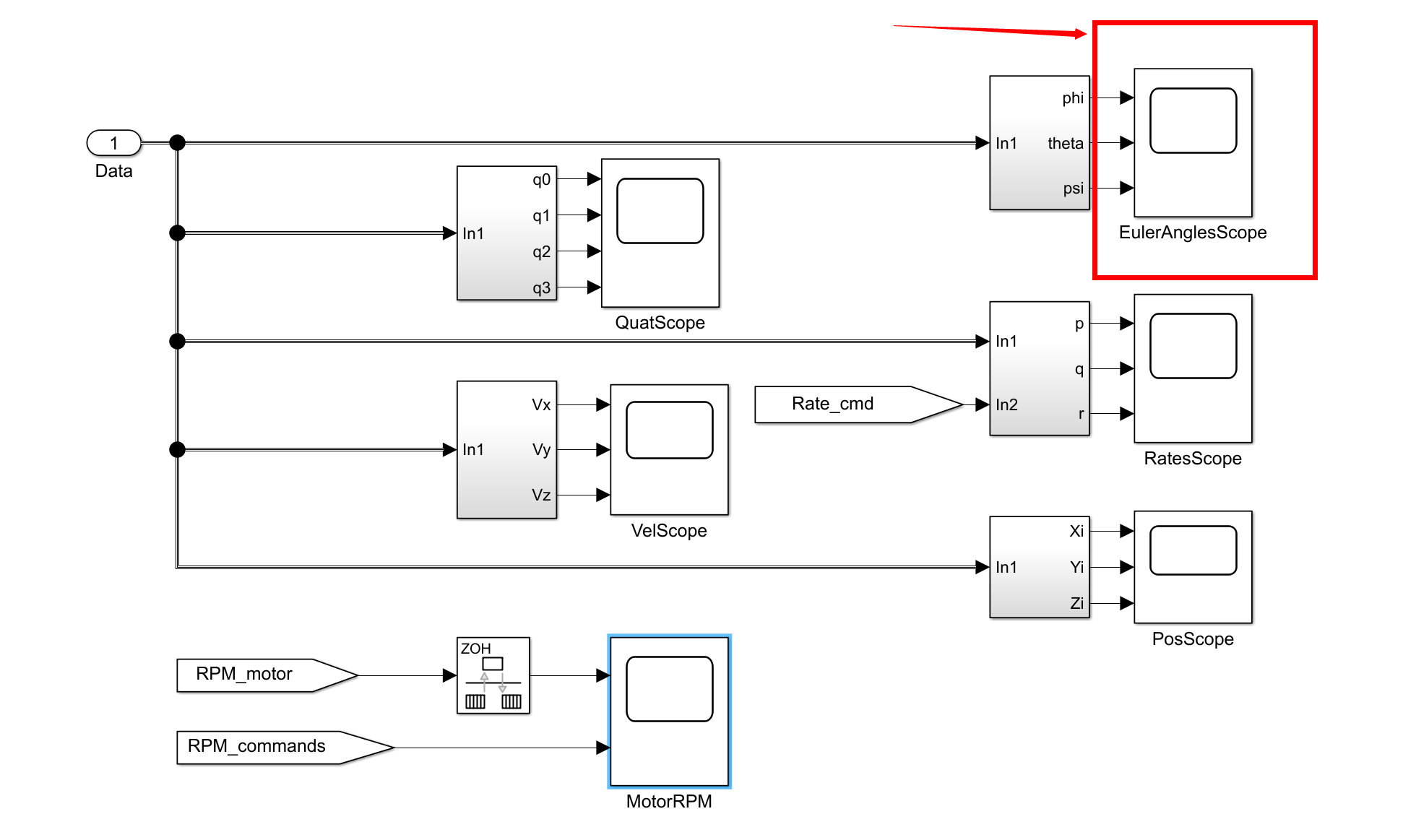
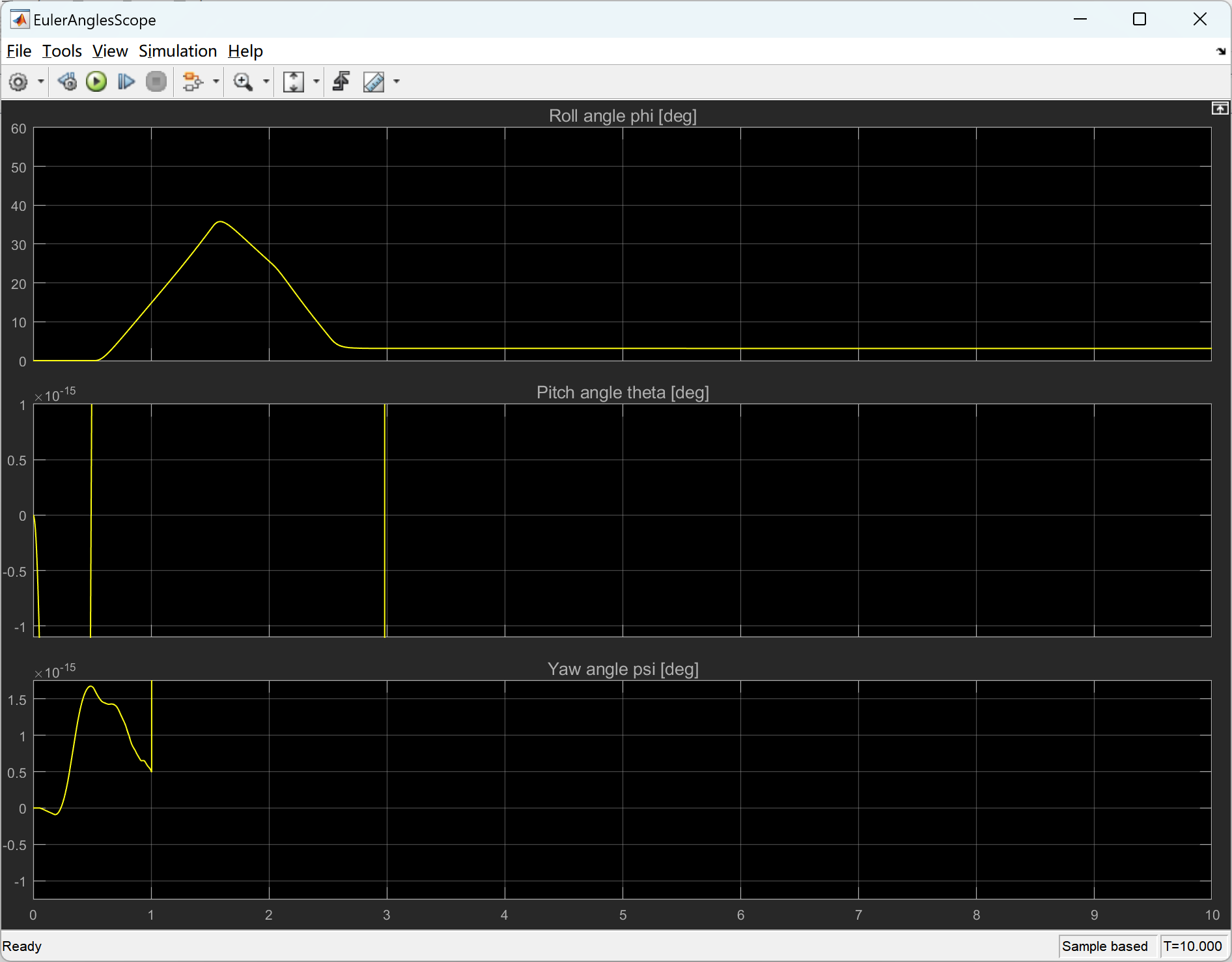
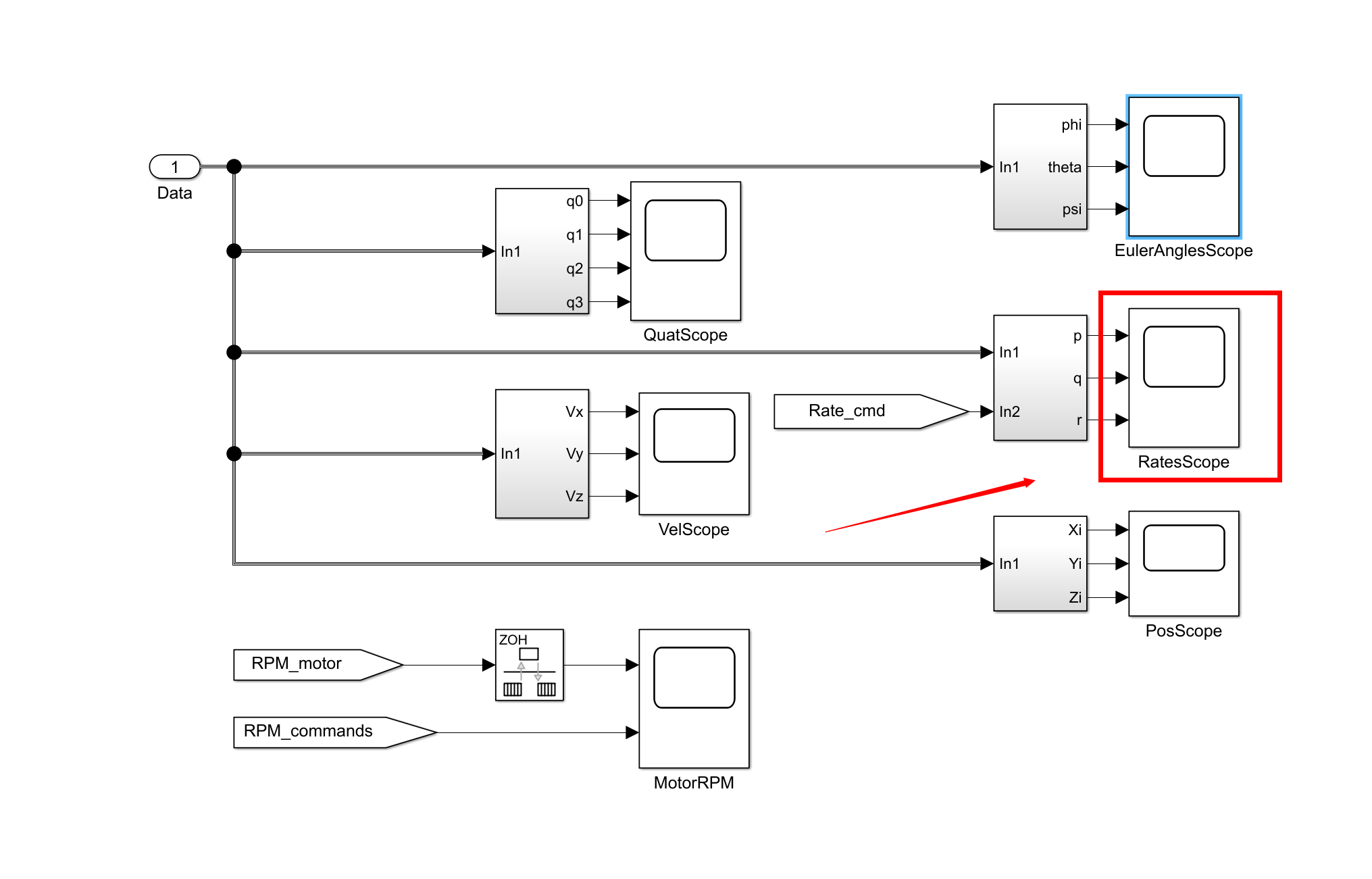
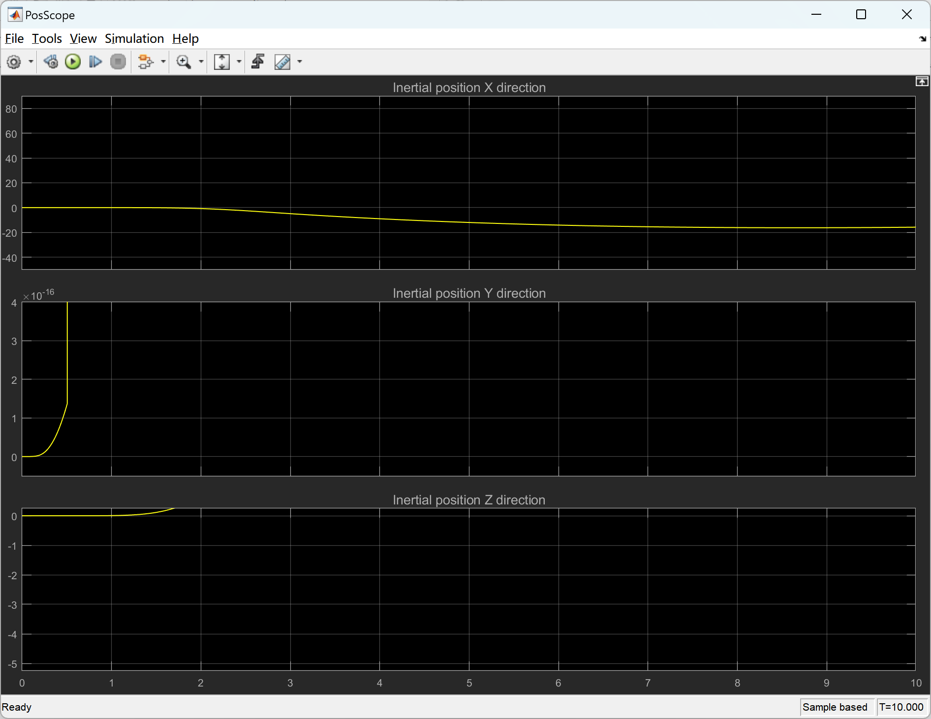
📚2 运行结果

部分代码:
clear all;close all;clc
%--------------------------------------------------------------------------
t_control = 1/500; % Controller/state estimation frequency 500Hz [s]
t_sim = t_control/2; % Simulation frequency 1000Hz [s]
sim_time = 10.0; % Duration of simulation [sec]
r2d = 180/pi; % Conversion factor radians to degrees [deg/rad]
d2r = pi/180; % Conversion factor degrees to radians [rad/deg]
g = 9.80665; % Acceleration of gravity [m/s^2]
rpm2radpersec = 2*pi/60; % Conversion factor RPM to rad/sec [rad/(s*rpm)]
rho = 1.225; % Density of air [kg/m^3]
%--------------------------------------------------------------------------
%%%%%%%%%%%%%%%%%%%%%%%%%%%%%%%%%%%%%%%%%%%%%%%%%%%%%%%%%%%%%%%%%%%%%%%%%%%
% Quad specific configuration parameters %
%%%%%%%%%%%%%%%%%%%%%%%%%%%%%%%%%%%%%%%%%%%%%%%%%%%%%%%%%%%%%%%%%%%%%%%%%%%
% The coordinate system used in this model is defined as follows:
% X: pointing forward, Roll axis
% Y: pointing to the right, Pitch axis
% Z: pointing down, Yaw axis
% To define the geometry of the airframe, the following convention is used:
% - the base airframe is assumed to be somewhat symmetric
% - the CoG for the base airframe coincides with the geometric center in X/Y plane (but is shifted along Z axis)
% - the motor arm length in X/Y plane is defined as the distance to the geometric center of the base airframe
% - motor thrust is generated at the prop, which is offset a distance (along Z) from the geometric center
% - motor thrust vector may be misaligned from purely Z direction, so a set of rotation angles is given for each motor
% - real position of CoG is given as a position vector from geometric center
% - everything is expressed in body coordinate system described above
%%%%%%%%%%%%%%%%%%%%%%%%%%%%%%%%%%%%%%%%%%%%%%%%%%%%%%%%%%%%%%%%%%%%%%%%%%%
Noise_flag = 0; % Set to 1 for sensor/estimation noise, to 0 for no noise
Coriolis_correction = 1; % Set to 1 to cancel omega x (J*omega) term in control law, 0 if not
Dyn_thrust = 0; % Set to 1 to engage dynamic thrust effects, to 0 to disengage
Blade_flapping = 0; % Set to 1 to engage blade flapping effects, to 0 to disengage
%%%%%%%%%%%%%%%%%%%%%%%%%%%%%%%%
% Initial conditions
Att_init = [0;0;0] * d2r; % Initial airframe attitude in Euler angles Roll/Pitch/Yaw for 6DOF block [deg]
omega_init = [0;0;0]; % Initial angular rates in Body frame for 6DOF block [rad/s]
Vb_init = [0;0;0]; % Initial velocity in Body frame for 6DOF block [m/s]
Xi_init = [0;0;0]; % Initial position in Inertial frame for 6DOF block [m]
rpm_init = 3104.5025852; % Initial motor speed [rpm]
q_init = rpy2quat(Att_init); % Compute the initial attitude quaternion
R_IB_init = rpy2rot(Att_init); % Compute the initial rotation matrix R_IB
Vi_init = R_IB_init' * Vb_init; % Compute the initial velocity in Inertial axes
%%%%%%%%%%%%%%%%%%%%%%%%%%%%%%%%
% Parameters for aerodynamic drag computation
a = 0.060; % Surface area of airframe visible along the Body x axis [m^2]
b = 0.060; % Surface area of airframe visible along the Body y axis [m^2]
c = 0.060; % Surface area of airframe visible along the Body z axis [m^2]
C_D = 0.40; % Drag coefficient [dimensionless]
Surface_params = [a;b;c]; % Combine the surface area parameters
%%%%%%%%%%%%%%%%%%%%%%%%%%%%%%%%
% Parameters for dynamic thrust computation
v_h = 4.0; % Induced aerodynamic velocity at hover [m/s]
kappa = 1.00; % Value for induced power factor in hover (chosen to make transition from different states continuous)
k1 = -1.125; % Empirical values taken from Hoffmann_2011
k2 = -1.372; % Empirical values taken from Hoffmann_2011
k3 = -1.718; % Empirical values taken from Hoffmann_2011
k4 = -0.655; % Empirical values taken from Hoffmann_2011
%%%%%%%%%%%%%%%%%%%%%%%%%%%%%%%%
% Parameters for blade flapping computation
k_a1s = 1.5 / 4.0; % Gain in linear relationship between wind velocity and flapping angle [deg/(m/s)]
k_beta = 0.23; % Stiffness of the propeller blades [Nm/rad]
%%%%%%%%%%%%%%%%%%%%%%%%%%%%%%%%
% Real airframe data
CoG_real = [0;0;0.001]; % Location of center of gravity w.r.t. geometric center (in Body axes) [m]
mass_real = 0.550; % Complete airframe mass [kg]
Jxx = 0.003960; %
Jxy = 0; %
Jxz = 0; %
Jyx = 0; %
Jyy = 0.003845; % Moment of inertia for multirotor w.r.t center of gravity [kg*m^2]
Jyz = 0; %
Jzx = 0; %
Jzy = 0; %
Jzz = 0.007350; %
J_real = [Jxx Jxy Jxz;Jyx Jyy Jyz;Jzx Jzy Jzz]; % Moment of inertia matrix
%%%%%%%%%%%%%%%%%%%%%%%%%%%%%%%%
% MotorMatrix_real holds all the information about the actual performance
% of each actuator. The data is arranged as one row per motor/prop combo:
% 1 : Motor arm angle measured clockwise (looking from above) from the positive X axis (forward direction) [deg]
% 2 : Distance of prop/motor in X/Y plane from the geometric center of the airframe [m]
% 3 : Distance of prop/motor in Z direction from the geometric center of the airframe [m]
% 4 : Direction of prop rotation: -1 for CW, +1 for CCW [unitless]
% 5 : Control effectiveness of the actuator (nominally 1.0)
% 6 : First-order motor transfer function time constant [sec]
% 7..8 : Two coefficients that describe the RPM to thrust [N] transfer function for static conditions [a1 a2]
% Thrust = a1 * RPM + a2 * RPM^2
% 9..10 : Two coefficients that describe the RPM to torque [Nm] transfer function for static conditions [b1 b2]
% Torque = b1 * RPM + b2 * RPM^2
% 11 : Minimum RPM value of the actuator
% 12 : Maximum RPM value of the actuator
% 13..15 : Rotations of thrust vector around Body-fixed axes away from nominal direction [deg]
% Nominal direction of thrust vector is [0;0;-1]
% Rotation order from body to motor axes is Yaw/Pitch/Roll (Euler angle sequence (1,2,3))
% 16 : Propeller diameter [m]
% 17 : Propeller mass [kg]
MotorMatrix_real = [045 , 0.170 , -0.028 , -1 , 1.0 , 0.010 , [9.6820 , 0.010872]*1e-5 , [1.4504 , 0.0016312]*1e-6 , 0000 , 6000 , [0.0 , 0.0 , 0.0] , 8*2.54/100 , 11/1000; ...
135 , 0.170 , -0.028 , +1 , 1.0 , 0.010 , [9.6820 , 0.010872]*1e-5 , [1.4504 , 0.0016312]*1e-6 , 0000 , 6000 , [0.0 , 0.0 , 0.0] , 8*2.54/100 , 11/1000; ...
225 , 0.170 , -0.028 , -1 , 1.0 , 0.010 , [9.6820 , 0.010872]*1e-5 , [1.4504 , 0.0016312]*1e-6 , 0000 , 6000 , [0.0 , 0.0 , 0.0] , 8*2.54/100 , 11/1000; ...
315 , 0.170 , -0.028 , +1 , 1.0 , 0.010 , [9.6820 , 0.010872]*1e-5 , [1.4504 , 0.0016312]*1e-6 , 0000 , 6000 , [0.0 , 0.0 , 0.0] , 8*2.54/100 , 11/1000];
%%%%%%%%%%%%%%%%%%%%%%%%%%%%%%%%
% Nominal airframe data (without disturbance/uncertainties)
CoG_nominal = [0;0;0.001]; % Location of center of gravity w.r.t. geometric center (in Body axes) [m]
mass_nominal = 0.550; % Complete airframe mass [kg]
Jxx = 0.003960; %
🎉3 参考文献
文章中一些内容引自网络,会注明出处或引用为参考文献,难免有未尽之处,如有不妥,请随时联系删除。
[1]李佳欢,王新华,周城宇,等.多旋翼无人机编队动态航路规划研究[J].电光与控制, 2018, 25(9):5.
[2]孔杰杰,王检耀,王鸿东.一种新型多旋翼无人机着舰装置及安全边界评估方法[J].中国舰船研究, 2022.
[3]李延锋,刘高洋,张铁国.低雷诺数多旋翼农用无人机改进翼型气动仿真分析[J].设计, 2017(11):3.


 789
789

 被折叠的 条评论
为什么被折叠?
被折叠的 条评论
为什么被折叠?
 到【灌水乐园】发言


