


volumetric fog rendering
abstract:
the aim of this bachelor’s thesis is to describe the physical behavior of fog in real life and the algorithm for implementing fog in computer graphics applications. an implementation of the volumetric fog algorithm written in the unity game engine is also provided. the performance of the implementation is evaluated using benchmarks 基准, including an analysis of the results. additionally, some suggestions are made to improve the volumetric fog rendering in the future.
keywords:
computer graphics, fog, volumetrics, lighting
1. introduction
as the computational power of graphics cards increases, computer games can use more demanding and physically-based real-time rendering techniques to bring out the visual quality of those games. one such effect is fog rendering. in the past, fog has been mainly used to mask the shortcomings of computer hardware[1]. an example of this is the computer game Silent hill [2][3]. nowdays, fog can be realistically simulated and made to interact with light.
the objective of this thesis is to explain how fog behaves in real life and to provide an algorithm for rendering realistic fog in computer graphics. the thesis also comes with a descrption of the implementation of the algorithm.
The first chapter of this thesis explains the theory behind fog in real life. The second chapter describes the algorithm for rendering volumetric fog. The third chapter focuses on describing the implementation of the algorithm. The final chapter discusses the results and contains benchmarks of the author’s implementation and gives some suggestions on how to improve the algorithm in the future.
1.1 fog rendering techniques
historically, the render distance in video games has been low, because computers were not as powerful as they are today. to save performance, the camera’s maximum rendering distance was set closer to the camera. by doing this, most of the scene geometry farther away would be clipped by the camera’s far plane and thus not rendered. this produced an effect known as “pop-in”, where the objects suddenly appeared in the camera’s view if the camera was close enough.
the solution to this was to fade each pixel on the screen to a predetermined color when it was farther than a fixed distance from the camera (a technique also known as depth fog). this made the popping effect go away and gave the scene a certain atmoshpere. figure 1 shows how depth was used in Silent Hill to make an impression that the game took place in a location covered by thick fog.
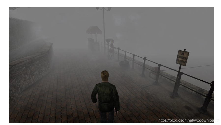
Figure 1. Depth fog in Silent Hill
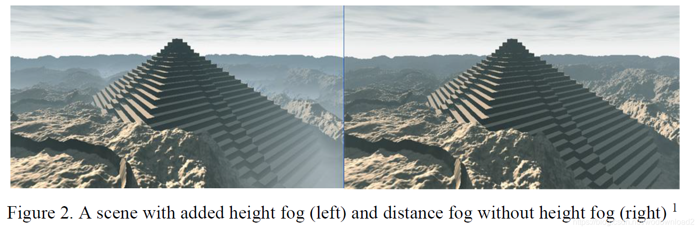
an improvement to rendering depth fog is to add height based fog, shown in figure 2. height fog makes the fog look more physically correct than just using depth fog by simulating the gathering of fog particles near the ground. for that, the height fog uses the world space Y axis coordinate to reduce the fog thickness according to height.
the advantage of height and depth fog is that they are cheap to compute and give rather good-looking results. the disadvantage of these methods is that they have uniform fog denstiy, which means that they can not be animated. in addition, the height and depth fog are calcualted only once per pixel thus they can not be used to represent light passing through them.
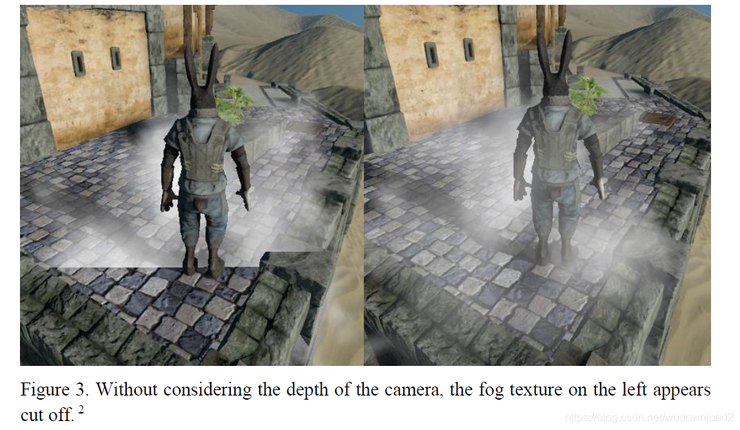
a solution to the animation problem is to use billboards. a billboard is a quad with a 2D texture placed on it that rotates so that it is always facing towards the camera. by using a billboard with a semi-transparent fog texture placed in a scene, realistic looking animated fog can be achieved by scolling the texture in some axis. the downside to this method is that whenever another surface intersects with a billboard, it produces a hard edge, which breaks the immersion浸入. in figure 3 the picture on the left has a sharp intersection between the ground geometry and the billboard. this can be solved by sampling the depth buffer and adjusting the opacity of the billboard according to how far it is from the object behind it this technique is also called soft particles.
Additionally, drawing multiple semi-transparent textures over each other causes a lot of pixel overdraw, which means that the color and alpha values of a pixel get overwritten many times. This might also decrease the rendering performance severely 严重的.
even by using soft particles, billboards still cannot represent how light propagates through a volume. for this reason, a new technique called volumetric fog was created. volumetric fog is used in computer graphics to simulate how fog particles interact with light in real life.
2. volumetric fog theory
it is not feasible to simulate every fog particle separately. instead, volumetric fog estimates the density of fog particles in a relatively small space. the density is then used to calculate the physical interaction of the fog particles with the incoming light, namely transmission, absorption, and scattering of the light. this simulation is performed only for the world regions visible to the camera; therefore, the space under observation is the camera view volume. the camera view volume is split into uniform chunks, where the X and Y dimensions of a chunk are equal to the size of a pixel and the Z dimension of a chunk is calculated according to the size of the volume in the Z axis.
figure 4 shows that light entering a volume can be either out-scattered, in-scattered, absorbed or transmitted [4].
a) out-scattering is the scattering of light back towards the light source.
b) in-scattering is the scattering of light towards the viewer.
c) absorption is the loss of light energy upon interaction with a particle.
d) transmittance shows how much light energy is transmitted after all the other processes have taken place.
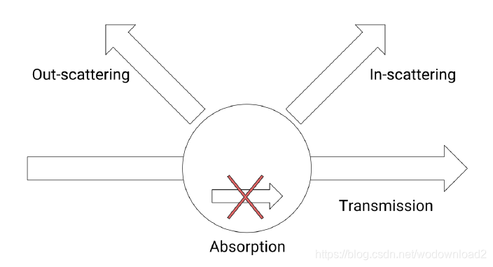
figure 4. different ways how light can interact with a particle.
according to Wronski [5], this process can be statistically modeled for each point of the volume using Equation 1.

where Ltransmitted is the transmittance of light, Labsorbed is the absorption and Lscattered is the sum of in-scattered and out-scattered light.
2.1 atmosphere scattering
since the earth is surrounded by an atmosphere, the light particles coming from the sun and entering the eye of the viewer must interact with the atmosphere first. this means that some of the light gets scattered into the surrrounding medium. however, the particles found in the atmosphere does not scatter all wavelengths of light equally: shorter wavelengths are scattered more. because the codler colors have shorter wavelengths, they get scattered more and this is the reason why the sky is blue[6]. figure 5 shows the color of the atmosphere during a clear day.
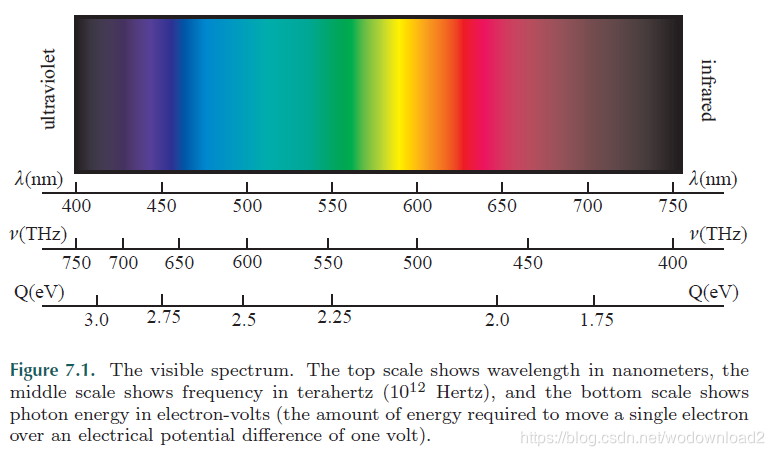

Figure 5. Blue sky due to scattering of light in the atmosphere
Wronski[5] says that the amount of light participating in the scattering process can be different. for example, there exists Rayleigh scattering. it is the scattering of low wavelength particles in the atmosphere and is responsible for the blue color of the atmosphere [7]. in computer graphics, phase functions are used to describe the angular distribution of light scattered in each direction[8].
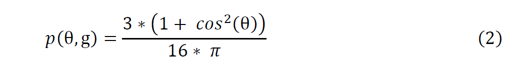
equation 2 defines the function for calculating the Rayleigh phase function, where θ repre-sents the angle between the direction of light and the direction of the viewer and g∈[-1,1] represents anisotropy 各向异性. anisotropy describes the directional dependency of the scattered light, which means that light scatters more in one direction[4].
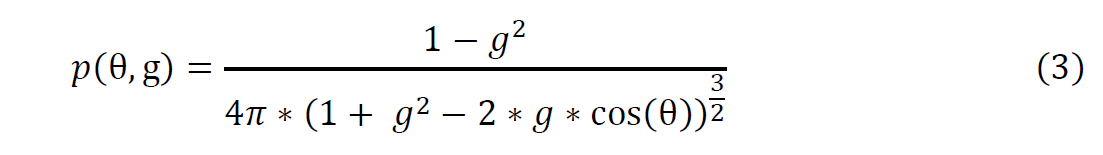
there also exists Mie scattering, which is the scattering of bigger wavelength particles [4]. Mie scattering is too expensive to compute in real-time and thus a phase function is used to represent Mie scattering. the most common phase function used to approximate Mie scattering is the Henyey-Greenstein phase function.[8][9]
Equation 3 defines the function for calculating the value of Henyey-Greenstein phase func-tion. The parameters are same as used for the Rayleigh phase function.
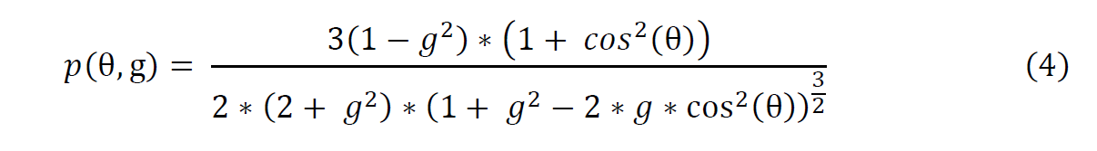
according to Cornette and Shanks [10], the Henyey-Greenstein phase function does not consider small particles illuminated by unpolarized light. in their paper, the authors propose of a more physically-based phase function, which has a similar form to the Henyey-Green-stein phase function. this means the Cornette-Shanks phase function can be easily used as a replacement for the Henyey-Greenstein phase function. equation 4 defines the Cornette-Shanks phase function using the same parameters as the Henyey-Greenstein phase function and the Rayleigh phase function.
to model the transmittance of incoming light, the Beer-Lamber law is used.[5] the Beer-Lambert law states that light transmittance is exponential to the distance traveled by light inside a medium.

equation 5 defines the function used to calcualte Beer-Lambert law. βe is the sum of scattering and absorption coefficients. the law is used to calcualte the transmittance of light energy at each point of the participating medium.
3. algorithm for rendering volumetric fog
the algorithm for rendering volumetric fog
a) sampling the noise,
b) sampling the shadow map,
c) adding lighting,
d) applying blur to the fog,
e) blending the rendering to the screen.
3.1 noise
in real life, fog does not have uniform density: some areas of the fog volume are denser and others are sparser. to mimic this characteristic in computer graphics, different noise generation algorithms are used, also known as noise functions. noise functions are functions that return a continuous value in response to an input given to them. noise functions are deterministic 确定的 , but they still have some structure to them, making them perfect for representing fog in computer graphics.
a common way to create procedure textures is to precompute the noise using noise functions and save it to a texture, reducing the overall performance cost. multiple noise textures can also be combined to get interesting effects like variable fog densities. another advantage of noise function is that they can be precomputed and stored in the computer’s memory, reducing the overrall performance cost of the algorithm. the noise texture used for the algorithm can be seen in figure 6.
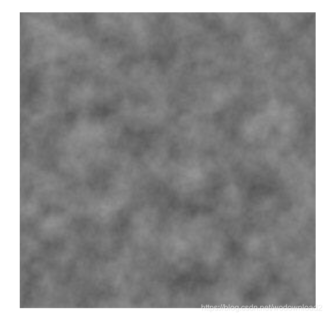
figure 6. the noise texture the fog is sampled from
3.2 sampling the noise
a 2D texture with precomputed noise values in the range of 0 to 1 is used to calculate the fog density at each point of the volume. the colors of a fog texture can be interpreted in different ways, but in this thesis, they represent fog density at some point in the fog. a value of 1 represents complete fogging at that point (transmittance is 0), meaning that nothing can be seen through it. a value of 0 represents no fogging at that point (transmittance is 1). values between 0 and 1 get increasingly denser, meaning that less and less of geometry behind the fog can be seen. the value of a sample is also based on height, meaning that fog farther from the reference level will be less dense. the fog density is then used to calculate how much light ineracts with that particle. this is done by shooting rays through the volume and accumulating the result along the way.
3.3 sampling the shadow map
in this part of the algorithm, the locations of the shadows are calcualted. for this, a shadow map is sampled so that the fog algorithm can decide if a point in the volume is in shadow. the result is then saved into a texture and used in the next parts of the algorithm. this step is responsible for the light shafts 光束 that represent the edges of shadows.
3.4 adding lighting
in this part of the algorithm, the extinction, scattering and transmittance are calcualted. the extinction values are constant for each point in the volume, so it can be represented as a coefficient multiplied by the fog density. the scattering value is calculated by summing up the values of the Cornette-Shanks phase function and Rayleigh phase function. the transmittance is calcualted by appling Beer’s law to the sample.
3.5 applying blur to the fog
during light transport, some of the light gets scattered into the surrouding medium in real life, which creates a hazy effect to the fog. in computer graphics, this phenomemon is simulating by using blur. the blur effect is created by taking the values of surrounding pixels on the screen and interpolating the color values bewteen them. as a result, a color of a pixel is now the weighted average of nearby pixel.s
3.6 blending and rendering to the screen
the final step of the algorithm is to blend the fog with the existing scene geometry. it is done by sampling the surface color and additively blending it with the fog color. the transmittance of the fog is contained in the fog texture alpha value. the lower the transmittance, the denser the fog is at that point, which means that less of the background geometry is visible to the camera.
4. implementation
the algorithm is implemented in the unity game engine 5. in unity, a C# script is used for setting up the necessary context, passing values to the shaders and storing the intermediate results in textures. shaders are used to render the fog, add blur and blend it with existing scene geometry.
4.1 architecture
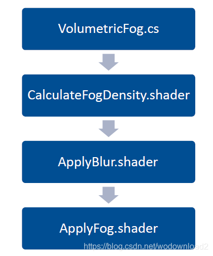
figure 7. the architecture of the program used for rendering volumetric fog.
the architecture of the fog implementation in unity can be seen in figure 7. first, the C# script VolumetricFog.cs takes the parameters and sends them to the shaders. all the shaders are post-effect shaders, meaning that they change the pixel colors of an already rendered scene. the fog is rendered using the CalculateFogDensity.shader script. the result is stored in a texture and used in the ApplyBlur.shader script. this script is run many times to get an increasingly blurrier fog effect. finally, the previous result is used in the ApplyFog.shader script to blend the fog with the scene geometry. after each frame, the render textures used are temporarily freed so they do not take up memory once they are not needed anymore.
4.2 raymaching
intergrating the fog volume is done by casting a ray for each pixel of the screen and during multiple iterations, moving along the ray by a pre-calculated step size. the ray is then extended until transmittance reaches 0 or a maximum predefined number of steps is reached. this technique is also known as raymarching. raymarching is used to accumulated fog density for each pixel separately.
float rayMarch(steps, direction, startPos)
{
	// calcualte the pixel depth using the uv of the pixel and the depth texture
	depth = calcualte_pixel_depth();
	// maps the depth value to range [0,1]
	depth = linearise_depth(depth);
	// get the world space coordinates of the pixel
	endPos = viewPos_to_worldPos(depth);
	rayLength = length(endPos - startPos);
	// divide the steps evenly along the ray length
	stepSize = rayLength / steps;
	result = 0;
	// start marching from the camera position
	currentPos = startPos;
	for(i=0; i<steps; i++)
	{
		currentResult = 0;
		noise = sample_noise(currentPos);
		currentResult = calcualte_shadows_and_lighting(currentPos, noise);
		// add current result to the overall result
		result += currentResult;
		// extend the ray by a step in the ray direction
		currentPos += direction*stepSize;
	}
	return result;
figure 8. the pseudocode used for raymarching.
figure 8 shows the pseudocode that is used by the CalcualteFogDensity shader to accumulate fog density and calculate lighting for each pixel.
4.3 sampling the shadow map and adding lighting
to sample from the shadow map, it first needs to be created and stored in a texture. unity generates the shadow maps automatically for the scene, but storing it to a texture needs to be done manually. this is done by creating a command buffer and setting it to execute after the shadow map has been created. a command buffer is a buffer used to hold a list of rendering commands, which can be set to execute at various points during the scene rendering, lighting rendering or be executed immediately [11].
void AddLightCommandBuffer()
{
	// create a command buffer and give it a global identifier
	_AfterShadowPass = new CommandBuffer {name = "Volumetric Fog ShadowMap"};
	// store the result in the shader texture “ShadowMap”
	_AfterShadowPass.SetGlobalTexture("ShadowMap",new RenderTargetIdentifier(BuiltinRenderTextureType.CurrentActive));
	Light sunLight = SunLight.GetComponent<Light>();
	if(sunLight)
	{
		// add the commnad buffer to the light and set it to execute after the shadow map has been generated by Unity
		sunLight.AddCommandBuffer(LightEvent.AfterShadowMap, _AfterShadowPass);
	}
}
figure 9. the code to set up a command buffer 6
figure 9 shows the code required to create a command buffer and attach it to a light. first, a new command buffer is created. after that, a render texture is created with the same parameters as the one currently being rendered to . this command buffer is then set to execute after the shadow map has been generated, saving the shadow map to a texture named “ShadowMap”.
Unity uses Cascading Shadow Maps (CSMs) [12], which means that different parts of the camera view frustum have different shadow map resolutions. This technique is useful be-cause usually the viewer can see details closer to them more clearly, but details farther away are harder to distinguish. The technique also increases the performance of using shadow maps because cascades farther away can be calculated with a smaller resolution.
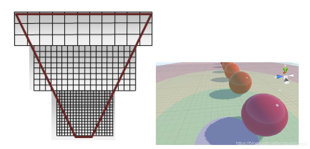
Figure 10. A top-down representation of a cascaded shadow map inside the camera view frustum7 (left) and a cascaded shadow map projected to the ground surface in Unity^8(right).
figure 10 shows that cascades closer to the camera have more resolution, while the cascades far away have a noticeably smaller resolution. on the right, the cascades are shown as seen in unity, where each color respresents a different cascade. the distance of each cascade from the camera can be adjusted.
fixed4 getCascadeWeights(float depth)
{
	float4 zNear = float4(depth >= _LightSplitsNear);
	float4 zFar = float4(depth < _LightSplitsFar);
	float4 weights = zNear * zFar;
	return weights;
}
Figure 11. The code used to sample cascade weights
According to the depth value of the current pixel, the world space coordinates of the pixel are calculated. The code in Figure 11 is used to select all the cascades that are between the cameras near and far plane.
fixed4 getShadowCoord(float4 worldPos, float4 weights)
{
	float3 shadowCoord = float3(0,0,0);
	if(weights[0] == 1)
	{
		shadowCoord += mul(unity_WorldToShadow[0], worldPos).xyz;
	}
	if(weights[1] == 1)
	{
		shadowCoord += mul(unity_WorldToShadow[1], worldPos).xyz;
	}
	if(weights[2] == 1)
	{
		shadowCoord += mul(unity_WorldToShadow[2], worldPos).xyz;
	}
	if(weights[3] == 1)
	{
		shadowCoord += mul(unity_WorldToShadow[3], worldPos).xyz;
		return float4(shadowCoord,1);
	}
Figure 12. The code used to get the correct shadow map coordinates


 1235
1235

 被折叠的 条评论
为什么被折叠?
被折叠的 条评论
为什么被折叠?
 到【灌水乐园】发言


