


https://catlikecoding.com/unity/tutorials/rendering/part-7/
1 directional shadows
while our lighting shader produces fairly realistic results by now, it evaluates each surface fragment in isolation. it assumes that a ray of light from every light source eventually hits every fragment. but this is only true it those rays are not blocked by sth.
when an object sits in between a light source and another object, it might prevent part or all of the light rays from reaching that other object. the rays that illuminate the first object are no longer available to illuminate the second object. as a result, the second object will at least partially unlit. the area that is not lit lies in the shadow of the first object. to describe this, we often say that the first object casts a shadow on the second one.
in reality, there is transition region between fully lit and fully shadowed space, know as the penumbra. it exits because all light sources have a volume. as a result, there are regions where only part of the light source is visible, which means that they are partially shadowed. the larger the light source, and the further away a surface is from its shadow caster, the larger this region is.
unity does not support penumbra. unity does support soft shadows, but that is a shadow filtering technique, not a simulation of penumbra.
1.1 enabling shadows
without shadows, it is hard to see the spatial relationships between objects. to illustrate this, i create a simple scene with a few stretched cubes. i placed four rows of spheres above these cubes. the middle rows float of spheres, while the outer rows are connected to the cubes below them via cylinders.
the objects have unity’s default white material. the scene has two directional lights, the default directional light, and a slightly weaker yellow light. these are the same lights in previous tutorials.
currently, the shadows are disabled project-wide. we did that in an earlier tutorial. the ambient intensity is also set to zero, which makes it easier to see the shadows.
shadows are part of project-wide quality 根据项目设置的 settings, found via edit/project settings/quality. we will enable them at a high quality level. this means supporting both hard and soft shadows, using a high resolution, a stable fit projection, a distance of 150, and four cascades.
make sure that both lights are set to cast soft shadows. their resolution should depend on the quality settings.
with both directional lights casting shadows, the spatial relationships between all objects becomes a lot clearer. the entire scene has become both more realistic and more interesting to loot at.
1.2 shadow mapping
how does unity add these shadows to the scene ?? the standard shader apparently has some way to determine whether a ray is blocked or not.
u could figure this out whether a point lies in a shadow, by casting a ray through the scene, from the light to the surface fragment. if that ray hits sth. before it reaches the fragment, then it is blocked. this is sth. that a physics engine could do, but it would be very impractical 不切实际的 to do so for each fragment, and per light. and then u would have to get the results to the gpu somehow.
there are a few techniques to support real-time shadows. each has it advantages and disadvantages. unity uses the most common technique nowdays, which is shadow mapping. this means that unity stores shadow information in textures, somehow. we will now investigate how that works.
open the frame debugger via window/frame debugger, enable it, and look at the hierarchy of rendering steps. look at the differences between a frame without and a frame with shadows enabled.
when shadows are disabled, all objects are rendered as usuall. we were already familiar with this process. but when shadows are enabled, the process becomes more complex. there are a few more rendering phases, and quite a lot more draw calls. shadows are expensive.
1.3 rendering to the depth texture
when directional shadows are enabled, unity begins a depth pass into the rendering pass. the result is put into a texture that matches the screen resolution. this pass renders the entire scene, but only records the depth information of each fragment. this is the same information that is used by the gpu to determine whether a fragment ends up on top or below a previously rendered fragment.
this data corresponds with a fragment’s z coordinate, in clip space. this is the space that defines the area that camera can see. the depth information ends up stored as a value in the 0-1 range. when viewing the texture, nearby texels appear dark. the further away a texel is, the lighter it becomes.
what is clip space??
it is the space that determines what the camera sees. when u select the main camera in the scene view, u will see a pyramid wire frame in front of it, which indicates what it can see.
in clip space, this pyramid is a regular cube. the mode-view-projection matrix is used to convert mesh vertices to this space. it is known as clip space, because everything that ends up outside of this cube gets clipped, because it is not visible.
this information actually has nothing to do with shadows directly, but unity will use it in a later pass.
1.4 rendering to shadow maps
the next thing unity renders is the shadow map of the first light. a little later, it will render the shadow map of the second light as well.
again, the entire scene is rendered, and again only the depth information is stored in a texture.
however, this time the scene is rendered from the point of the view of light source. effectively, the light act as a camera. this means that the depth value tells us how far a ray of light traveled before it hit sth. this can used to determine if sth. is shadowed.
what about normal maps??
the shadow maps record the depth of the actual geometry. normals maps add the illusion of a rough surface, and shadow maps ignore them. thus, shadows are not affected by normal maps.
because we are using directional lights, their cameras are orthographic. as such, there is no perspective projection. and the exact position of the light’s camera does not matter. unity will position the camera so it sees all objects that are in view of the normal camera.
actually, it turns out that unity does not just render the entire scene once per light. the scene is rendered four times per light. the textures are split into four quadrants, each being rendered to from a different point of view. this happens because we have opted to use four shadow cascades. if u were to switch to two cascades, the scene would be rendered twice per light. and without cascades, it is only rendered once per light. we will see why unity does this when we look at the quality of shadows.
1.5 collecting shadows
we have the depth information of the scene, from the point of view of the camera. we also have this information from the point of view of each light. of course this data is stored in different clip spaces, but we know the relative positions and orientations of these spaces. so we can convert from one space to the other. this allows us to compare the depth measurements from both points of view. conceptually, we have to vectors that should end up at the same point. if they do, both the camera and light can see that point, and so it is lit. if the light’s vector ends before reaching the point, then the light is blocked, which means that point is shadowed.
what about when the scene camera can not see a point??
those points are hidden behind other points that are closer to the camera. the scene’s depth texture only contains the closest points. as a result, no time is wasted on evaluating hidden points.
unity creates these textures by rendering a single quad that covers the entire view. it uses the hidden/internal-screenspaceshadows shader fro this pass. each fragment samples from the scene’s and light’s depth textures, makes the comparison, and renders the final shadow value to a screen-space shadow map. lit texels are set to 1, and shadowed texels are set to 0. at this point unity can also perform filtering, to create soft shadows.
why does unity alternate between rendering and collecting???
each light needs its own screen-space shadow map. but the shadow map rendered from the light’s point of view can be reused.
这个是啥意思。。。
1.6 sampling the shadow maps
finally, unity is finished rendering shadows. now the scene is rendered normally, with one change. the light colors are multiplied by the values stored in their shadow maps. this eliminates the light when it should be blocked.
every fragment that gets rendered samples the shadow maps. also fragments that end up hidden behind other objects that are drawn later. so these fragments can end up receiving the shadows of the objects that end up hiding them. u can see this when stepping through the frame debugger. u can also see shadows appear before the objects that actually cast them. of course these mistakes only manifest while rendering the frame. once it is finished the image is correct.
1.7 shadow quality
when the scene is rendered from the light’s point of view, the orientation does not match the scene camera. so the texels of shadow maps do not align with the texels of the final image. the resolution of the shadow maps also ends up being different. the resolution of the final image is determined by the display settings. the resolution of the shadow maps is determined by the shadow quality settings.
when the texels of the shadow maps end up rendered larger than those of the final image, they will become noticeable. the edges of the shadows will be aliased. this is most obvious when using hard shadows.
to make this as obvious as possible, change the shadow quality settings so we only get hard shadows, at the lowest resolution, with no cascades.
it is now very obvious that the shadows are textures. also, bits of shadow are appearing in places where they should not. we will look into that later.
the closer the shadows get to the scene camera, the larger their texels become. that is because the shadow map currently covers the entire area visible to the scene camera. we can increase the quality close to the camera, by reducing the area that is covered by shadows, via the quality settings.
by limiting shadows to an area close to the scene camera, we can use the same shadow maps to cover a much smaller area. as a result, we get better shadows. but we lose the shadows that are further away. the shadows fade away as the approach the maximum distance.
ideally, we get high-quality shadows up close, while also keeping the shadows that are far away. because far away shadows end up rendered to a smaller screen area, those could make do with a lower-resolution shadow map. this is what shadow cascades do. when enabled, multiple shadow maps are rendered into the same texture. each map is use at a certain distance.
when using four cascades, the result looks a lot better, even though we are still using the same texture resolution. we are just using the texels much more efficiently. the downside is that we now have to render the scene three more times.
when rendering to the screen-space shadow maps, unity takes care of sampling from the correct cascade. u can find where one cascade ends and another begins, by looking for a sudden change of the shadow texel size.
u can control the range of the cascade bands via the quality settings, as portions of the shadow distance. u can also visualize them in the scene view, by changing its shading mode. instead of just shaded, use miscellaneous/shadow cascades. this will render the colors of the cascade on top of the scene.
the shape of the cascade bands depends on the shadow projection quality setting. the default is stable fit. in this mode, the bands are chosen based on the distance to the camera’s position. the other option is close fit, which uses the camera’s depth instead. this produces rectangular bands in the camera’s view direction.
这句话的意思是:shadow projection的模式影响band的的形状。
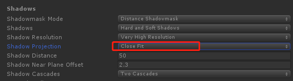
当为close fit的时候,那么band为矩形:

这个要在:
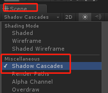
要在scene视图中,将show cascades显示出来,才能看到cascade的形状。
而如果shadow projection为stable fit的时候:
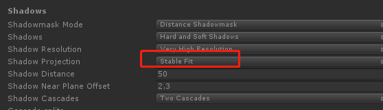

形状变了,不知道背后的原理是啥,有待研究。
this configuration allows more efficient use of the shadow texture, which leads to higher-quality shadows. however, the shadow projection now depends on the position and orientation of the camera. as a result, when the camera moves or rotates, the shadow maps changes as well. if u can see the shadow texels, u will notice that they move. this effect is known as shadow edge swimming, and can be very obvious. that is why the other mode is the default.
下面,我们就来看看stable fit和close fit的区别。
我们的测试场景很简单:
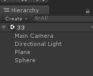
就是一个平面、一个球体、一个摄像机、一个平行光
然后关键是灯光的设置,如果设置不好,可能就不会看到这个效果:edge swimming.

为啥要把:shadow type改为:hard shadows,因为软阴影的话,则边缘被平滑处理了。
其他的bias、normal bias都是将其设置为0,使其有粉刺
综上,这些设置都是想让其阴影的边缘更加清晰可见,好观察其移动闪烁的效果。
最后我们还要写个让摄像机转动的脚本:
public class RoateCamera : MonoBehaviour {

    public Camera camera;
    public Transform target;
    public float speed = 5;

	void Update ()
    {
        camera.transform.RotateAround(target.transform.position, Vector3.up, Time.deltaTime * speed);
	}
}
将其拖拽大场景的任意物体上,赋值好摄像机、已经目标,这里我们让摄像机围绕着球体转动,所以目标即为球体。
尽量的让摄像机拉近点,好看到锯齿的边:

设置阴影的投影方式为close fit:

上图我们看到了锯齿的边了吧,最后运行程序:
可以看到边缘确实在闪烁了。
将阴影投影方式改为:stable fit,可以看到编译确实稳定下来了。
综上,我们我们默认的方式应该选择stable fit方式。
1.8 shadow ance
when we used low quality hard shadows, we saw bits of shadow appear where they should not.
unfortunately, this can happen regardless of the quality settings.
原因之一——一个像素代表一片区域而不是一个点
each texel in the shadow map represents the point where a light ray hit a surface. however, texels are not single points. they end up covering a larger area. and they are aligned with the light direction, not with the surface. as a result of this, they can end up sticking in, through, and out of surfaces like dark shards 黑斯碎片. as 就好像 parts of the texels end up poking out 凸出 of the surfaces that cast the shadow, the surface appears to shadow itself. 这样表面给自己投影了。this is known as shadow acne.
原因之二——数字精度问题
another source of shadow acne is numberical precision limitations 数字精度限制. these
limitations can cause incorrect result when very small distances are involved.
the shadow bias is configured per light, and is set to 0.05 by default.
上面是调整bias的值,可以看到影子的锯齿效果。
a low bias can produce shadow acne, but a large bias introduces another problem. as the shadow-casting objects are pushed away from the lights, 物体被推开了,离光源更远了。so are their shadows. as a result, the shadows will not be perfectly aligned with the objects. this is not so bad when using a small bias. but when the bias is too large shadows will appear disconnected from the objects that cast them, which is known as peter panning.
besides this distance bias, there is also a normal bias. this is a subtler adjustment of the shadow casters. this bias pushes the vertices of the shadow caster inwards, along their normals. 让顶点沿着法线缩小了。this also reduces self-shadowing, but it also makes the shadows smaller and can cause holes to appear in the shadows.
注意点:bias是对每个灯都可以调节的。
1.9 anti-aliasing
do you have anti-aliasing enabled in the quality settings??

if u have, then u might have spotted another problem of shadow maps. they do not mix with the standard anti-aliasing approach.
when u enable anti-aliasing in the quality settings, unity will use multi-sampling anti-aliasing, MSAA.
it removes the aliasing at triangle edges by performing some super-sampling along those edges. 去除三角形边的锯齿。
the details do not matter here. what matters is that when unity renders the screen-space shadow maps, it does so with a single quad that covers the entire view. as a result, there are no triangle edges,and thus MSAA does not affect the screen-space shadow map.
MSAA does work for the final image, but the shadow values are taken straight from the screen-space shadow map.
this becomes very obvious when a light surface next to a darker surface is shadowed. the edge between the light and dark geometry is anti-aliased, while the shadow edge is not.


可以看到开启了抗锯齿,对于阴影来说是不起作用的。而对于物体是起作用的。
anti-aliasing methods that rely on image post-processing – like fxaa – do not have this problem, because they are applied after the entire scene has been rendered.
2 casting shadows
now that we know how unity creates shadows for directional lights, it is time to support add support for them to our own shader. currently, My First Lighting Shader neither casts nor received shadows.
let us deal with casting shadows first. i have changed the spheres and cylinders in the example scene to they use our material. so now they no longer cast shadows.
we know that unity renders the scene multiple times for directional shadows. once for the depth pass, and once per light, for each shadow map cascade. the screen-space map is a screen-space effect and does not concern us.
to support all relevant passes, we have to add a pass to our shader, with its light mode set to ShadowCaster. because we are only interested in the depth values, it will be a lot simpler than our other passes.
SubShader {

		Pass {
			Tags {
				"LightMode" = "ForwardBase"
			}

			…
		}

		Pass {
			Tags {
				"LightMode" = "ForwardAdd"
			}

			…
		}

		Pass {
			Tags {
				"LightMode" = "ShadowCaster"
			}

			CGPROGRAM

			#pragma target 3.0

			#pragma vertex MyShadowVertexProgram
			#pragma fragment MyShadowFragmentProgram

			#include "My Shadows.cginc"

			ENDCG
		}
	}
let us give the shadow programs their own include file, named My Shadows.cginc. they are very simple. the vertex program converts the position from object space to clip space as usual, and does nothing else. the fragment program actually does not need to do anything, so just return zero. the gpu records the depth value for us.
#if !defined(MY_SHADOWS_INCLUDED)
#define MY_SHADOWS_INCLUDED

#include "UnityCG.cginc"

struct VertexData {
	float4 position : POSITION;
};

float4 MyShadowVertexProgram (VertexData v) : SV_POSITION {
	return mul(UNITY_MATRIX_MVP, v.position);
}

half4 MyShadowFragmentProgram () : SV_TARGET {
	return 0;
}

#endif
this is already enough to cast shadows directional.
2.1 bias
we also have to support the shadow bias. during the depth pass, the biases are zero, but when rendering the shadow maps, the biases correspond to the light settings. we do so by applying the depth bias to the position in the vertex shader, in clip space.
to support the depth bias, we can use the UnityApplyLinearShadowBias function, which is defined in UnityCG.
float4 MyShadowVertexProgram (VertexData v) : SV_POSITION {
	float4 position = mul(UNITY_MATRIX_MVP, v.position);
	return UnityApplyLinearShadowBias(position);
}
to also support the normal bias, we have to move the vertex position based on the normal vector. so we have to add the normal to our vertex data. then we can use the UnityClipSpaceShadowCasterPos function to apply the bias. this function is also defined in UnityCG.
struct VertexData {
	float4 position : POSITION;
	float3 normal : NORMAL;
};

float4 MyShadowVertexProgram (VertexData v) : SV_POSITION {
	float4 position = UnityClipSpaceShadowCasterPos(v.position.xyz, v.normal);
	return UnityApplyLinearShadowBias(position);
}
our shader is now a fully functional shadow caster.
3 receiving shadows
the second part of the process is receiving shadows. all objects in the test scene now use our material.
这里的平面也换成我们的shader。由于没有添加接收阴影的,所以无法看到阴影了。
let us first concern ourselves with the shadows of the main directional light only. because this light is included in the base pass, we have to adjust that one.
when the main directional light casts shadows, unity will look for a shader variant that has the SHADOW_SCREEN keyword enabled. so we have to create two variants of our base pass, one with and one without this keyword. this works the same as for the VERTEXLIGHT_ON keyword.
#pragma multi_compile _ SHADOWS_SCREEN
#pragma multi_compile _ VERTEXLIGHT_ON
the pass now has tow multi-compile directives, each for a single keyword. as a result, there are four possible variants. one with no keywords, one for each keyword, one with both keywords.
// Snippet #0 platforms ffffffff:
SHADOWS_SCREEN VERTEXLIGHT_ON

4 keyword variants used in scene:

<no keywords defined>
VERTEXLIGHT_ON
SHADOWS_SCREEN
SHADOWS_SCREEN VERTEXLIGHT_ON
after adding the multi-compile pragma, the shader compiler will complain about a nonexistent _ShadowCoord. this happens because the UNITY_LIGHT_ATTENUATION macro behaves differently when shadows are in play. to quickly fix this, open the My Lighting.cginc file and just set the attenuation to 1 when we have shadows.
#if defined(SHADOWS_SCREEN)
		float attenuation = 1;
	#else
		UNITY_LIGHT_ATTENUATION(attenuation, 0, i.worldPos);
	#endif
3.1 sampling shadows
to get to the shadows, we have to sample the screen-space shadow map. to do this, we need to know the screen-space texture coordinates. like other texture coordinates, we will pass them from the vertex shader to the fragment shader. so we need use an additional interpolator when supporting shadows. we will begin by just passing along the homogeneous clip-space position, so we need a float4.
struct Interpolators {
	…

	#if defined(SHADOWS_SCREEN)
		float4 shadowCoordinates : TEXCOORD5;
	#endif

	#if defined(VERTEXLIGHT_ON)
		float3 vertexLightColor : TEXCOORD6;
	#endif
};

…

Interpolators MyVertexProgram (VertexData v) {
	…

	#if defined(SHADOWS_SCREEN)
		i.shadowCoordinates = i.position;
	#endif

	ComputeVertexLightColor(i);
	return i;
}
we can access the screen-space shadows via _ShadowMapTexture. it is defined in AutoLight when appropriate. the naive approach is to simply use the clip-space XY coordinates of the fragment to sample this texture.
UnityLight CreateLight (Interpolators i) {
	…

	#if defined(SHADOWS_SCREEN)
		float attenuation = tex2D(_ShadowMapTexture, i.shadowCoordinates.xy);
	#else
		UNITY_LIGHT_ATTENUATION(attenuation, 0, i.worldPos);
	#endif

	…
}
we are now sampling shadows, but with clip-space coordinates instead of screen-space coordinates. we do get shadows, but they end up compressed into a tiny region at the center of the screen. we have to stretch them to cover the entire window.
in clip space, all visible XY coordinates fall inside the -1~1 range, while the range for screen-space is 0-1. the first step to solve this by having XY. next, we also have to offset the coordinates so they are zero at the bottom-left corner of the screen. because we are dealing with a perspective transformation, how much we must offset the coordinates depends on how far away they are. in this case, the offset is equal to the fourth homogeneous coordinate, before halving.
#if defined(SHADOWS_SCREEN)
		i.shadowCoordinates.xy = (i.position.xy + i.position.w) * 0.5;
		i.shadowCoordinates.zw = i.position.zw;
	#endif
the projection is still not correct, because we are using homogeneous coordinates. we have to convert to screen-space coordinates, by dividing X and Y by W.
The result gets distorted. The shadows are stretched and curved. This happens because we do the division before interpolation. This is incorrect, the coordinates should be interpolated independently, before the division. So we have to move the division to the fragment shader.
我们要在片段着色器中进行透视除法,因为要在插值之后才能做透视除法。否则在顶点着色器中直接透视除法了,会导致影子延伸和扭曲。
i.shadowCoordinates.xy = (i.position.xy + i.position.w) * 0.5 / i.position.w;
我们来解释下上面发生了什么。
首先在顶点着色器中:
i.shadowCoordinates.xy = (i.position.xy + i.position.w) * 0.5;
i.shadowCoordinates.zw = i.position.zw;
此时点的坐标为:(x/2 + w/2 ,y/2 + w/2, z, w)
在片段着色器中:
进行透视除法,除以w得到:
(x/2w+0.5, y/2w+0.5, z/w, 1)
解释完毕,之所以,i.shadowCoordinates.zw = i.position.zw;是为了在片段着色器中进行透视除法使用,除以第四维w。
Interpolators MyVertexProgram (VertexData v) {
	…

	#if defined(SHADOWS_SCREEN)
		i.shadowCoordinates.xy =
			(i.position.xy + i.position.w) * 0.5; // / i.position.w;
		i.shadowCoordinates.zw = i.position.zw;
	#endif

	…
}

UnityLight CreateLight (Interpolators i) {
	…

	#if defined(SHADOWS_SCREEN)
		float attenuation = tex2D(
			_ShadowMapTexture,
			i.shadowCoordinates.xy / i.shadowCoordinates.w
		);
	#else
		UNITY_LIGHT_ATTENUATION(attenuation, 0, i.worldPos);
	#endif

	…
}
how does interpolation affect division??
this is best illustrated with an example, suppose that we are interpolating between the xw coordinate pairs (0,1) and (1,4). no matter how we do this, X/W starts at 0 and ends at 1/4. but what about halfway between those points??
if we divide before interpolating, then we end up halfway between 0 and 1/4, which is 1/8.
if we divide after interpolating, then the halfway point we end up with the coordinates (0.5, 2.5), which is 1/5,not 1/8. 这里x=0+1=1, w=1+4=5,中点为(0.5, 2.5),然后除以w得到0.5/2.5。 so in this case the interpolation is not linear.

at this point, your shadows will either appear correct, or upside down. if they are flipped, it means that your graphics api-direct 3d-- has the screen-space y coordinates go from 0 to 1 downwards, instead of upwards. to synchronize with this, flip the Y coordinate of the vertex.
i.shadowCoordinates.xy = (float2(i.position.x, -i.position.y) + i.position.w) * 0.5;
3.2 using unity’s code
unity’s include file provide a collection of functions and macros to help us sample shadows. they take care of api differences and platform limitations. for example, we can use the ComputeSreenPos function from UnityCG.
#if defined(SHADOWS_SCREEN)
		i.shadowCoordinates = ComputeScreenPos(i.position);
	#endif
the AutoLight include file defines three usefull macros. they are SHADOW_COORDS, TRANSFER_SHADOW, and SHADOW_ATTENUATION. when shadows are enabled, these macros perform the same work that we just did. they do nothing when there are no shadows.
SHADOW_COORD defines the interpolator for shadow coordinates, when needed. it uses the _ShadowCoord name, which was what the compiler complained about earlier.
struct Interpolators {
	…

//	#if defined(SHADOWS_SCREEN)
//		float4 shadowCoordinates : TEXCOORD5;
//	#endif
	SHADOW_COORDS(5)

	…
};
TRANSFR_SAHDOW fills these coordinates in the vertex program.
Interpolators MyVertexProgram (VertexData v) {
	…

//	#if defined(SHADOWS_SCREEN)
//		i.shadowCoordinates = i.position;
//	#endif
	TRANSFER_SHADOW(i);

	…
}
and SHADOW_ATTENUATOIN uses the coordinates to sample the shadow map in the fragment program.
UnityLight CreateLight (Interpolators i) {
	…

	#if defined(SHADOWS_SCREEN)
		float attenuation = SHADOW_ATTENUATION(i);
	#else
		UNITY_LIGHT_ATTENUATION(attenuation, 0, i.worldPos);
	#endif

	…
}
actually, the UNITY_LIGHT_ATTENUATION maro already uses SHADOW_ATTENUATION. that is why we got that compiler error before. so we can suffice with using just that macro. the only change is that we have to use the interpolators as its second argument, while we just used zero before.
UNITY_LIGHT_ATTENUATION(attenuation, i, i.worldPos);
after rewriting our code to use these macros, we get new compile errors. this happens because unity’s macros unfortunately make assumptions about the vertex data and interpolator structures. first, it is assumed that the vertex position is named vertex, while we named it position. second, it is assumed that the interpolator position is named pos, but we named it position.
let us be pragmatic and adopt these names too. they are only used in a few places anyway, so we do not have to change much.
struct VertexData {
	float4 vertex : POSITION;
	…
};

struct Interpolators {
	float4 pos : SV_POSITION;
	…
};

…

Interpolators MyVertexProgram (VertexData v) {
	Interpolators i;
	i.pos = mul(UNITY_MATRIX_MVP, v.vertex);
	i.worldPos = mul(unity_ObjectToWorld, v.vertex);
	…
}
our shadows should work again, and this time on as many platforms as unity supports.
3.3 multiple shadows
the main directional light is now casting shadows, but the second directional light still does not. that is because we do not yet define SHADOWS_SCREEN in the additive pass. we could add a multi-compile statement to it, but SHADOWS_SCREEN only works for directional lights. to get the correct combination of keywords,change the existing multi-compile statement to one that also includes shadows.
#pragma multi_compile_fwdadd_fullshadows
this adds four additional keywords into the mix, to support different light types.
上面的意思是说,我们要在add通道添加关键字SHADOWS_SCREEN,但是它只能用于平行灯,所以为了支持其他的类型的灯,则简单的方法是使用:multi_compile_fwdadd_fullshadows
4 spotlight shadows
now that we have dealt with directional lights, let us move on to spotlights. disable the directional lights and add some spotlights with shadows to the scene. surprise! thanks to unity’s macros, spotlight shadows already work.
when looking at the frame debugger, u will see that unity does less work for spotlight shadows. there is no separate depth pass, no screen-space shadow passes. only the shadow maps are rendered.
聚光灯不能支持级联阴影。
the shadow maps works the same as for directional lights. they are depth maps, rendered from the light’s point of view. however, there are big differences between a directional light a spotlight. the spotlight has an actual position, and its light rays are not parallel. so the spotlight’s camera has a perspective view, and can not be move (原文是more) around arbitrarily. as a result, these lights can not support shadow cascades.
although the camera setup is different, the shadow casting code is identical for both light types. the normal bias is only supported for directional shadows, but it is simply set to zero for other lights.
4.1 sampling the shadow map
because spotlights do not use screen-space shadows, 聚光灯不用屏幕空间的阴影,the sampling code has to be different. but unity’s macros hide this difference from us.
we found directional shadows by simply sampling the screen-space shadow map. unity took care of shadow filtering when creating that map, so we do not need to worry about that. however, spotlights do not use screen-space shadows. so if we want to use soft shadows, we have to do the filtering in the fragment program.
then SHADOW_ATTENUTATION macro uses the UnitySampleShadowmap function to sample the shadow map. this function is defined in UnityShadowLibrary, which AutoLight includes. when using hard shadows, the function samples the shadow map once. when using soft shadows, it samples the map four times and averages the result. the result is not as good as the filtering used for screen-space shadows, but it is a lot faster.
5 point light shadows
now try some point lights. when u enable shadows for a point light, u will be greeted with a compile error. apparently, UnityDecodeCubeShadowDepth is undefined. this error happens because UnityShadowLibrary depends on UnityCG, but does not explicitly include it. so we have to make sure that UnityCG is included first. we can do this by including UnityPBSLighting before including AutoLight in My Lighting.
#include "UnityPBSLighting.cginc"
#include "AutoLight.cginc"
//#include "UnityPBSLighting.cginc"
it compiles, but all objects in range of the lights end up black. there is sth. wrong with the shadow maps.
when u inspect the shadow maps via the frame debugger, u will discover that not one, but six maps are rendered per light. this happens because point lights shine in all directions. as a result, the shadow map has to be a cube map. cube maps are created by rendering the scene with the camera pointing in six different directions, once per face of the cube. so shadows for point lights are expensive.
5.1 casting shadows
unfortunately, unlit does not use depth cube maps. apparently, not enough platforms support them. so we can not rely on the fragment’s depth value in My Shadows. instead, we will have to output the fragment’s distance as the result of the fragment program.
when rendering point light shadow maps, unity looks for a shadow caster variant with the SHADOW_CUBE keyword be defined. the SHADOWS_DEPTH keyword is used for directional and spotlight shadows. to support this, add a special multi-compile directive for shadow casters to our pass.
Pass {
			Tags {
				"LightMode" = "ShadowCaster"
			}

			CGPROGRAM

			#pragma target 3.0

			#pragma multi_compile_shadowcaster

			#pragma vertex MyShadowVertexProgram
			#pragma fragment MyShadowFragmentProgram

			#include "My Shadows.cginc"

			ENDCG
		}
this adds the variants that we need.
// Snippet #2 platforms ffffffff:
SHADOWS_CUBE SHADOWS_DEPTH

2 keyword variants used in scene:

SHADOWS_DEPTH
SHADOWS_CUBE
because points lights require such a different approach, let us create a separate set of program function for them.
#if defined(SHADOWS_CUBE)

#else
	float4 MyShadowVertexProgram (VertexData v) : SV_POSITION {
		float4 position =
			UnityClipSpaceShadowCasterPos(v.position.xyz, v.normal);
		return UnityApplyLinearShadowBias(position);
	}

	half4 MyShadowFragmentProgram () : SV_TARGET {
		return 0;
	}
#endif
to figure out a fragment’s distance from the light, we have to construct the world-space vector from the light to the fragment. we can do so by creating these vectors per vertex, and interpolating them. this requires an additional interpolator.
#if defined(SHADOWS_CUBE)
	struct Interpolators {
		float4 position : SV_POSITION;
		float3 lightVec : TEXCOORD0;
	};

	Interpolators MyShadowVertexProgram (VertexData v) {
		Interpolators i;
		i.position = UnityObjectToClipPos(v.position);
		i.lightVec =
			mul(unity_ObjectToWorld, v.position).xyz - _LightPositionRange.xyz;
		return i;
	}

	float4 MyShadowFragmentProgram (Interpolators i) : SV_TARGET {
		return 0;
	}
#else
in the fragment program, we take the length of the length of the light vector and add the bias to it. then we divide that by light’s range to fit them in the 0-1 range. the _LightPositionRange.w variable contains the inverse of its range, so we have to multiply by this value. the result is output as a floating-point value.
float4 MyShadowFragmentProgram (Interpolators i) : SV_TARGET {
		float depth = length(i.lightVec) + unity_LightShadowBias.x;
		depth *= _LightPositionRange.w;
		return UnityEncodeCubeShadowDepth(depth);
	}
5.2 sampling the shadow maps
now that our shadow maps are correct, the point light shadows appear. unity’s macros take care of the sampling of those maps.
just like with spotlight shadows, the shadow map is sampled once for hard shadows, and four times for soft shadows. the big difference is that unity does not support filtering for the shadow cube maps. as a result, the edges of the shadows are much harsher. so point light shadows are both expensive and aliased.


 5508
5508


 被折叠的 条评论
为什么被折叠?
被折叠的 条评论
为什么被折叠?
 到【灌水乐园】发言


