


Textures are an important and fundamental aspect of real-time rendering in general,
and OpenGL in particular. The use of textures within a shader opens up a huge range of
possibilities. Beyond just using textures as sources of color information, they can be used for
things like depth information, shading parameters, displacement maps, normal vectors, or
other vertex data. The list is virtually endless. Textures are among the most widely used tools
for advanced effects in OpenGL programs, and that isn’t likely to change anytime soon.
In OpenGL 4, we now have the ability to read and write to memory
via buffer textures, shader storage buffer objects, and image
textures (image load/store). This further muddies the waters of
what exactly defines a texture. In general, we might just think of it
as a buffer of data that may or may not contain an image.
OpenGL 4.2 introduced immutable storage textures. Despite what the term may imply,
immutable storage textures are not textures that can’t change. Instead, the term immutable
refers to the fact that, once the texture is allocated, the storage cannot be changed. That is,
the size, format, and number of layers are fixed, but the texture content itself can be modified.
The word immutable refers to the allocation of the memory, not the contents of the memory.
Immutable storage textures are preferable in the vast majority of cases because of the
fact that many run-time (draw-time) consistency checks can be avoided, and you include a
certain degree of “type safety,” since we can’t accidentally change the allocation of a texture.
Throughout this book, we’ll use immutable storage textures exclusively.
Immutable storage textures are allocated using the glTexStorage*
functions. If you’re experienced with textures, you might be accustomed to
using glTexImage* functions, which are still supported, but create mutable
storage textures.
In this chapter, we’ll look at some basic and advanced texturing techniques. We’ll start with
the basics, just applying color textures, and move on to using textures as normal maps and
environment maps. With environment maps, we can simulate things like reflection and
refraction. We’ll see an example of projecting a texture onto objects in a scene similar to
the way that a slide projector projects an image. Finally, we’ll wrap up with an example of
rendering directly to a texture(using framebuffer objects (FBOs) and then applying that
texture to an object.
Applying a 2D texture
In GLSL, applying a texture to a surface involves accessing texture memory to retrieve a color
associated with a texture coordinate, and then applying that color to the output fragment.
The application of the color to the output fragment could involve mixing the color with the
color produced by a shading model, simply applying the color directly, using the color in the
reflection model, or some other mixing process. In GLSL, textures are accessed via sampler
variables. A sampler variable is a “handle” to a texture unit. It is typically declared as a uniform
variable within the shader and initialized within the main OpenGL application to point to the
appropriate texture unit.
In this recipe, we’ll look at a simple example involving the application of a 2D texture to a
surface as shown in the following image. We’ll use the texture color to scale the color provided
by the ambient, diffuse, and specular (ADS) reflection model. The following image shows the
results of a brick texture applied to a cube. The texture is shown on the right and the rendered
result is on the left.
Set up your OpenGL application to provide the vertex position in attribute location 0, the
vertex normal in attribute location 1, and the texture coordinate in attribute location 2. The
parameters for the ADS reflection model are declared again as uniform variables within the
shader, and must be initialized from the OpenGL program. Make the handle to the shader
available in a variable named programHandle.
To render a simple shape with a 2D texture, use the following steps:’
- In your initialization of the OpenGL application, use the following code to load the
texture. (The following makes use of a simple TGA image loader, provided with the
sample code.)
GLint width, height;
GLubyte * data = TGAIO::read("brick1.tga", width, height);
// Copy file to OpenGL
glActiveTexture(GL_TEXTURE0);
GLuint tid;
glGenTextures(1, &tid);
glBindTexture(GL_TEXTURE_2D, tid);
glTexStorage2D(GL_TEXTURE_2D, 1, GL_RGBA8, w, h);
glTexSubImage2D(GL_TEXTURE_2D, 0, 0, 0, width, height,GL_RGBA, GL_UNSIGNED_BYTE, data);
glTexParameteri(GL_TEXTURE_2D, GL_TEXTURE_MAG_FILTER, GL_LINEAR);
glTexParameteri(GL_TEXTURE_2D, GL_TEXTURE_MIN_FILTER, GL_LINEAR);
delete [] data;
// Set the Tex1 sampler uniform to refer to texture unit 0
int loc = glGetUniformLocation(programHandle, "Tex1");
if( loc >= 0 )
	glUniform1i(loc, 0);
- Use the following code for the vertex shader:
layout (location = 0) in vec3 VertexPosition;
layout (location = 1) in vec3 VertexNormal;
layout (location = 2) in vec2 VertexTexCoord;
out vec3 Position;
out vec3 Normal;
out vec2 TexCoord;
uniform mat4 ModelViewMatrix;
uniform mat3 NormalMatrix;
uniform mat4 ProjectionMatrix;
uniform mat4 MVP;
void main()
{
	TexCoord = VertexTexCoord;
	Normal = normalize( NormalMatrix * VertexNormal);
	Position = vec3( ModelViewMatrix *
	vec4(VertexPosition,1.0) );
	gl_Position = MVP * vec4(VertexPosition,1.0);
}
- Use the following code for the fragment shader:
in vec3 Position;
in vec3 Normal;
in vec2 TexCoord;
uniform sampler2D Tex1;
struct LightInfo {
	vec4 Position; // Light position in eye coords.
	vec3 Intensity; // A,D,S intensity
};

uniform LightInfo Light;
struct MaterialInfo {
	vec3 Ka; // Ambient reflectivity
	vec3 Kd; // Diffuse reflectivity
	vec3 Ks; // Specular reflectivity
	float Shininess; // Specular shininess factor
};
uniform MaterialInfo Material;
layout( location = 0 ) out vec4 FragColor;
void phongModel( vec3 pos, vec3 norm,
out vec3 ambAndDiff, out vec3 spec ) {
// Compute the ADS shading model here, return ambient
// and diffuse color in ambAndDiff, and return specular
// color in spec
}
void main() {
	vec3 ambAndDiff, spec;
	vec4 texColor = texture( Tex1, TexCoord );
	phongModel(Position, Normal, ambAndDiff, spec);
	FragColor = vec4(ambAndDiff, 1.0) * texColor +
	vec4(spec, 1.0);
}
The first code segment demonstrates the steps needed to load the texture from a file, copy
the texture data to OpenGL memory, and initialize the sampler variable within the GLSL
program. The first step, loading the texture image file, is accomplished via a simple TGA image
loader that is provided along with the example code (TGAIO::read()). It reads the image
data from a file in the TGA format, and stores the data into an array of unsigned bytes in RGBA
order. The width and height of the image are returned via the last two parameters. We keep a
pointer to the image data, simply named data.
Experienced OpenGL programmers should be familiar with the next part of the code. First,
we call glActiveTexture to set the current active texture unit to GL_TEXTURE0 (the first
texture unit, also called a texture channel). The subsequent texture state calls will be effective
on texture unit zero. The next two lines involve creating a new texture object by calling
glGenTextures… The handle for the new texture object is stored in the variable tid.
Then, we call glBindTexture to bind the new texture object to the GL_TEXTURE_2D target.
Once the texture is bound to that target, we allocate immutable storage for the texture
with glTexStorage2D. After that, we copy the data for that texture into the texture object
using glTexSubImage2D. The last argument to this function is a pointer to the raw data for
the image.
The next steps involve setting the magnification and minimization filters for the texture object
using glTexParameteri. For this example, we’ll use GL_LINEAR.
Next, we delete the texture data pointed to by data. There’s no need to hang on to this,
because it was copied into texture memory via glTexSubImage2D.
Finally, we set the uniform variable Tex1 in the GLSL program to zero. This is our sampler
variable. Note that it is declared within the fragment shader with type sampler2D. Setting its
value to zero indicates to the OpenGL system that the variable should refer to texture unit zero
(the same one selected previously with glActiveTexture).
The vertex shader is very similar to the one used in previous examples except for the addition
of the texture coordinate input variable VertexTexCoord, which is bound to attribute
location 2. Its value is simply passed along to the fragment shader by assigning it to the
shader output variable TexCoord.
激活纹理单元、生产一个text,绑定texture,分配内存,拷贝数据,设置纹理格式,查找shader的纹理单元位置,将shader的纹理单元位置和激活的纹理单元挂钩。
The fragment shader is also very similar to those used in the recipes of previous chapters.
The important parts for the purpose of this recipe involve the variable Tex1. Tex1 is a
sampler2D variable that was assigned by the OpenGL program to refer to texture unit zero.
In the main function, we use that variable along with the texture coordinate (TexCoord)
to access the texture. We do so by calling the built-in function texture. This is a general
purpose function, used to access a texture. The first parameter is a sampler variable
indicating which texture unit is to be accessed, and the second parameter is the texture
coordinate used to access the texture. The return value is a vec4 containing the color
obtained by the texture access (stored in texColor), which in this case is an interpolated
value with the four nearest texture values (texels).
Next, the shading model is evaluated by calling phongModel and the results are returned in
the parameters ambAndDiff and spec. The variable ambAndDiff contains only the ambient
and diffuse components of the shading model. A color texture is often only intended to affect
the diffuse component of the shading model and not the specular. So we multiply the texture
color by the ambient and diffuse components and then add the specular. The final sum is
then applied to the output fragment FragColor.
There are several choices that could be made when deciding how to combine the texture color
with other colors associated with the fragment. In this example, we decided to multiply the
colors, but one could have chosen to use the texture color directly, or to mix them in some way
based on the alpha value.
Another choice would be to use the texture value as the value of the diffuse and/or specular
reflectivity coefficient(s) in the Phong reflection model. The choice is up to you!
Specifying the sampler binding within GLSL
As of OpenGL 4.2, we now have the ability to specify the default value of the sampler’s binding
(the value of the sampler uniform) within GLSL. In the previous example, we of set the value of
the uniform variable from the OpenGL side using the following code:
int loc = glGetUniformLocation(programHandle, "Tex1");
if( loc >= 0 )
	glUniform1i(loc, 0);
Instead, if we’re using OpenGL 4.2, we can specify the default value within the shader, using
the layout qualifier as shown in the following statement:
layout (binding=0) uniform sampler2D Tex1;
Thus simplifying the code on the OpenGL side, and making one less thing we need to worry
about. The example code that accompanies this book uses this technique to specify the value
of Tex1, so take a look there for a more complete example. We’ll also use this layout qualifier
in the following recipes.
applying multiple textures
the application of multiple textures of a surface can be used to create a wide variety of effects.
the base layer texture might represent the “clean” surface and the second layer could provide additional detail such as shadow, blemishes 斑点, roughness, or damage.
in many games, so-called light maps are applied as an additional texture layer to provide the information about light exposure, effectively producing shadows and shading without the need to explicityly calculate the reflection model.
these kinds of textures are sometimes referred to as “prebaked” lighting.
in this recipe, we will demonstrate this multiple texture technique by applying two layers of texture.
the base layer will be a fully opaque brick image, and the second layer will be one that is partically transparent.
the non-transparent parts look like moss 苔藓 that has grown on the bricks beneath.
the following image shows an example of multiple textures. the textures on the left are applied to the cube on the right.
the base layer is the brick texture, and the moss texture is applied on top.
the transparent parts of the moss texture reveal the brick texture underneath.

set up opengl application to provide the vertex position in attribute location 0, the vertex normal in attribute location 1, and the texture coordinate in attribtue location 2.
the parameters for the phong reflection model are declared as uinform variables within the shader and must be initialized from the opengl program.
to render objects with multiple textures, use the following steps:
- in the initialization section of your opengl program, load the two images into texture memory in the same way as indicated in the previous recipe applying a 2D texture.
make sure that the brick texture is loaded into texture unit 0 and the moss texture is in texture unit 1 use the following code to do this:
GLuint texIDs[2];
GLint w, h;
glGenTextures(2, texIDs);
// Load brick texture file
GLubyte * brickImg = TGAIO::read("brick1.tga", w, h);
// Copy brick texture to OpenGL
glActiveTexture(GL_TEXTURE0);
glBindTexture(GL_TEXTURE_2D, texIDs[0]);
glTexStorage2D(GL_TEXTURE_2D, 1, GL_RGBA8, w, h);
glTexSubImage2D(GL_TEXTURE_2D, 0, 0, 0, w, h, GL_RGBA,
GL_UNSIGNED_BYTE, brickImg);
glTexParameteri(GL_TEXTURE_2D, GL_TEXTURE_MAG_FILTER,
GL_LINEAR);
glTexParameteri(GL_TEXTURE_2D, GL_TEXTURE_MIN_FILTER,
GL_LINEAR);
delete [] brickImg;
// Load moss texture file
GLubyte * mossImg = TGAIO::read("moss.tga", w, h);
// Copy moss texture to OpenGL
glActiveTexture(GL_TEXTURE1);
glBindTexture(GL_TEXTURE_2D, texIDs[1]);
glTexStorage2D(GL_TEXTURE_2D, 1, GL_RGBA8, w, h);
glTexSubImage2D(GL_TEXTURE_2D, 0, 0, 0, w, h, GL_RGBA,GL_UNSIGNED_BYTE, mossImg);
glTexParameteri(GL_TEXTURE_2D, GL_TEXTURE_MAG_FILTER,
GL_LINEAR);
glTexParameteri(GL_TEXTURE_2D, GL_TEXTURE_MIN_FILTER,
GL_LINEAR);
delete [] mossImg;
- use the vertex shader from the previous applying a 2D texture.
- starting with the fragment shader from the recipe applying a 2D texture, replacing the declaration of the sampler variable Tex1 with the following code:
layout(binding=0) uniform sampler2D BrickTex;
layout(binding=1) uniform sampler2D MossTex;
- replace the main function in the fragment shader with the following code:
void main() {
vec3 ambAndDiff, spec;
vec4 brickTexColor = texture( BrickTex, TexCoord );
vec4 mossTexColor = texture( MossTex, TexCoord );
phongModel(Position, Normal, ambAndDiff, spec);
vec3 texColor = mix(brickTexColor, mossTexColor,
mossTexColor.a);
FragColor = vec4(ambAndDiff, 1.0) * texColor +
vec4(spec,1.0);
}
how it works?
the preceding code that loads the two textures into the opengl program is very similar to the code from the previous recipe applying a 2D texture.
the main difference is that we load each texture into a different texture unit.
when loading the brick texture, we set the opengl state such that the active texture unit is unit zero.
glActiveTexture(GL_TEXTURE0);
and when loading the second texture, we set the opengl state to texture unit one.
glActiveTexture(GL_TEXTURE1);
in step 3, we specify the texture binding for each sampler variable using the layout qualifier, cooresponding to the appropriate texture unit.
Within the fragment shader, we access the two textures using the corresponding uniform
variables, and store the results in brickTexColor and mossTexColor. The two colors are
blended together using the built-in function mix. The third parameter to the mix function
is the percentage used when mixing the two colors. The alpha value of the moss texture is
used for that parameter. This causes the result to be a linear interpolation of the two colors
based on the value of the alpha in the moss texture. For those familiar with OpenGL blending
functions, this is the same as the following blending function:
glBlendFunc( GL_SRC_ALPHA, GL_ONE_MINUS_SRC_ALPHA );
In this case, the moss color would be the source color, and the brick color would be the
destination color.
Finally, we multiply the result of the mix function by the ambient and diffuse components of
the Phong reflection model, add the specular component, and apply the result to the fragment.
In this example, we mixed the two texture colors together using the alpha value of the second
texture. This is just one of many options for mixing the texture colors. There are a number of
different choices here, and your choice will be dependent on the kind of texture data available
and the desired effect.
A popular technique is to use an additional vertex attribute to augment the amount of blending
between the textures. This additional vertex attribute would allow us to vary the blending factor
throughout a model. For example, we could vary the amount of moss that grows on a surface
by defining another vertex attribute, which would control the amount of blending between the
moss texture and the base texture. A value of zero might correspond to zero moss, up to a
value of one that would enable blending based on the texture’s alpha value alone.
using alpha maps to discard pixels
to create the effect of an object that has holes, we could use a texture with an appropriate alpha channel that contains information about the transparent parts of the object.
however, that requires us to make sure to make the depth buffer read-only.
and render all of our polygons from back to front in order to avoid blending problems.
we would need to sort our polygons based on the camera position and then render them in the correct order. what a pain!!!
with GLSL shaders, we can avoid all of this by using the discard keyword to completely discard fragments when the alpha value of the texture map is below a certain value.
by completely discarding the fragments, there is no need to modify the depth buffer because when discarded, they are not evaluated against the depth buffer at all.
we do not need to depth-sort our polygons because there is no blending.
the following image on the right shows the teapot with fragments discarded based upon the texture on the left. the fragment shader discards fragments that correspond to texels that have an alpha value below a certain threshold.

If we create a texture map that has an alpha channel, we can use the value of the alpha
channel to determine whether or not the fragment should be discarded. If the alpha value is
below a certain value, then the pixel is discarded.
As this will allow the viewer to see within the object, possibly making some back faces visible,
we’ll need to use two-sided lighting when rendering the object.
- Start with the same shader pair and set up from the previous recipe, Applying
multiple textures. - Load the base texture for the object into texture unit 0, and your alpha map into
texture unit 1.
To discard fragments based on alpha data from a texture, use the following steps: - Use the same vertex and fragment shaders from the recipe Applying multiple
textures. However, make the following modifications to the fragment shader. - Replace the sampler2D uniform variables with the following:
layout(binding=0) uniform sampler2D BaseTex;
layout(binding=1) uniform sampler2D AlphaTex;
- Replace the contents of the main function with the following code:
void main()
{
	vec4 baseColor = texture( BaseTex, TexCoord );
	vec4 alphaMap = texture( AlphaTex, TexCoord );
	if(alphaMap.a < 0.15 )
		discard;
	else
	{
		if( gl_FrontFacing )
		{
			FragColor = vec4(phongModel(Position,Normal),1.0 ) * baseColor;
		} else
		{
			FragColor = vec4(phongModel(Position,-Normal),1.0) *
			baseColor;
		}
	}
}
Within the main function of the fragment shader, we access the base color texture, and store
the result in baseColor. We access the alpha map texture and store the result in alphaMap.
If the alpha component of alphaMap is less than a certain value (0.15 in this example), then
we discard the fragment using the discard keyword.
Otherwise, we compute the Phong lighting model using the normal vector oriented appropriately,
depending on whether or not the fragment is a front facing fragment. The result of the Phong
model is multiplied by the base color from BaseTex.
This technique is fairly simple and straightforward, and is a nice alternative to traditional
blending techniques. It is a great way to make holes in objects or to present the appearance
of decay. If your alpha map has a gradual change in the alpha throughout the map, (for
example, an alpha map where the alpha values make a smoothly varying height field) then
it can be used to animate the decay of an object. We could vary the alpha threshold (0.15 in
the preceding example) from 0.0 to 1.0 to create an animated effect of the object gradually
decaying away to nothing.
using normal maps
normal mapping is a technique for faking variations in a surface that does not really exist in the geometry of the surface.
it is usefull for producing surfaces that have bumps, dents, roughness, or wrinkles without actually providing enough position information (vertices) to fully define those deformations.
the underlying surface is actually smooth, but is made to appear rough by varying the normal vectors using a texture (the normal map).
the technique is closely related to bump mapping or displacement mapping.
without normal maps, we modify the normal vectors based on information that is sotred in a texture.
this creates the appearance of a bump surface without actually providing the geometry of the bumps.
A normal map is a texture in which the data stored within the texture is interpreted as
normal vectors instead of colors. The normal vectors are typically encoded into the RGB
information of the normal map such that the red channel contains the x coordinate, the green
channel contains the y, and the blue channel contains the z coordinate. The normal map
can then be used as a “texture” in the sense that the texture values affect the normal vector
used in the reflection model rather than the color of the surface. This can be used to make
a surface look like it contains variations (bumps or wrinkles) that do not actually exist in the
geometry of the mesh.
The following images show an ogre mesh (courtesy of Keenan Crane) with and without a
normal map. The upper-left corner shows the base color texture for the ogre. In this example,
we use this texture as the diffuse reflectivity in the Phong reflection model. The upper right
shows the ogre with the color texture and default normal vectors. The bottom left is the
normal map texture. The bottom right shows the ogre with the color texture and normal map.
Note the additional detail in the wrinkles provided by the normal map.

a normal map can be produced in a number of ways. many 3D modeling programs such as Maya, Blender, or 3D Studio Max can generate normal maps. normal maps can also be generated directly from grayscale hightmap textures.
there is a NVIDA plugin for Adobe Photoshop that provides this functionality.
Normal maps are interpreted as vectors in a tangent space (also called the object local
coordinate system). In the tangent coordinate system, the origin is located at the surface
point and the normal to the surface is aligned with the z axis (0, 0, 1). Therefore, the x and y
axes are at a tangent to the surface. The following image shows an example of the tangent
frames at two different positions on a surface.

the advantage of using such a coordinate system lies in the fact that the normal vectors sotred within the normal map can be treated as perturbations of the ture normal, and are independent of the object coordinate system.
this saves us the need to transform the normals, add the perturbed normal, and renormalize.
instead, we can use the value in the norma map directly in the reflection model without any modification.
to make all of this work, we need to evaluated the reflection model in tangent space. in order to do so, we transform the vectors used in our reflection model into tangent space in the vertex shader, and then pass the along to the fragment shader where the reflection model wil be evaluated.
to define a transformation from the camera(eye) coordiante system to the tangent space coordinate system, we need three normalized, co-orthogonal vectors (defined in eye coordinates) that defined the tangent space systems.
the z axis is defined by the normal vector (n),
the x axis is defined by a vector called the tangent vector (t),
and the y axis is often called the binormal vector (b).
at point P, define in eye coordinates, could then be transformed into tangent space by multiplying by the following matrix:
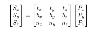
in the preceding equation, S is the point in tangent space and P is the point in eye coordiantes.
in order to apply this transformation within the vertex shader,the OpenGL
program must provide at least two of the three vectors that define the object local system
along with the vertex position. The usual situation is to provide the normal vector (n) and the
tangent vector (t). If the tangent vector is provided, the binormal vector can be computed as
the cross product of the tangent and normal vectors.
Tangent vectors are sometimes included as additional data in mesh data structures. If the
tangent data is not available, we can approximate the tangent vectors by deriving them from
the variation of the texture coordinates across the surface (see Computing Tangent Space
Basis Vectors for an Arbitrary Mesh, Eric Lengyel, Terathon Software 3D Graphics Library,
2001, at http://www.terathon.com/code/tangent.html).
in the following example, we will read the vertex position, normal vector, tangent vector, and texture coodinate in the vertex shader.
we will transform the position, normal, and tangent to eye space, and then compute the binormal vector (in eye space).
next, we will compute the viewing direction (v) and the direction towards the light source (s) in eye space, and then transform them to tangent space.
we will pass the tangent space v and s vectors and the (unchanged) texture coordinate to the fragment shader, where we will evaluate the phong reflection model, using the tangent space vectors and the normal vector retrieved from the normal map.
set up your opengl program to provide the position in attribute location 0, the normal in attribute location 1, the texture coordinate in location 2, and the tangent vector in location 3.
for this example, the fourth coordinate of the tangent vector should contain the “handedness” of the tangent coordinate system (either -1 or +1). this value will be multiplied by the result of the cross product.
load the normal map into texture unit one and the color texture into texture unit zero.
To render an image using normal mapping, use the following shaders:
layout (location = 0) in vec3 VertexPosition;
layout (location = 1) in vec3 VertexNormal;
layout (location = 2) in vec2 VertexTexCoord;
layout (location = 3) in vec4 VertexTangent;
struct LightInfo
{
	vec4 Position; // Light position in eye coords.
	vec3 Intensity; // A,D,S intensity
};
uniform LightInfo Light;
out vec3 LightDir;
out vec2 TexCoord;
out vec3 ViewDir;
uniform mat4 ModelViewMatrix;
uniform mat3 NormalMatrix;
uniform mat4 ProjectionMatrix;
uniform mat4 MVP;
void main()
{
	// Transform normal and tangent to eye space
	vec3 norm = normalize(NormalMatrix * VertexNormal);//vertexNormal是local的
	vec3 tang = normalize(NormalMatrix * vec3(VertexTangent)); //vertexTangent是local的,NormalMatrix=V*M,的左上角,所以可将local空间的dir转换到最终的view空间下
	//我们可以这样理解,将local的顶点位置,变换到view空间,需要经过两个步骤,首先是M变换到世界,然后是V变换到视空间。
	//而将local空间的方向,变换到view空间,需要MV的逆转矩阵,这里使用的是MV的左上角的3x3的矩阵代替。
	//由此可知,模型输入到顶点阶段的法线和切线都是模型空间的
	// Compute the binormal
	vec3 binormal = normalize( cross( norm, tang ) ) * VertexTangent.w;
	// Matrix for transformation to tangent space
	mat3 toObjectLocal = mat3(
	tang.x, binormal.x, norm.x,
	tang.y, binormal.y, norm.y,
	tang.z, binormal.z, norm.z ) ;
	// Get the position in eye coordinates
	vec3 pos = vec3( ModelViewMatrix * vec4(VertexPosition,1.0) );
	// Transform light dir. and view dir. to tangent space
	LightDir = normalize( toObjectLocal * (Light.Position.xyz - pos) );
	ViewDir = toObjectLocal * normalize(-pos); //这个地方有点疑惑,但是是正确的,因为点被转换到了view空间,此时摄像机的位置为(0,0,0),那么viewDir = 摄像机位置 - 顶点位置 = 也就是-pos
	// Pass along the texture coordinate
	TexCoord = VertexTexCoord;
	gl_Position = MVP * vec4(VertexPosition,1.0);
}
- Use the following code for the fragment shader:
in vec3 LightDir;
in vec2 TexCoord;
in vec3 ViewDir;
layout(binding=0) uniform sampler2D ColorTex;
layout(binding=1) uniform sampler2D NormalMapTex;
struct LightInfo
{
	vec4 Position; // Light position in eye coords.
	vec3 Intensity; // A,D,S intensity
};
uniform LightInfo Light;
struct MaterialInfo
{
	vec3 Ka; // Ambient reflectivity
	vec3 Ks; // Specular reflectivity
	float Shininess; // Specular shininess factor
};
uniform MaterialInfo Material;
layout( location = 0 ) out vec4 FragColor;
vec3 phongModel( vec3 norm, vec3 diffR )
{
	vec3 r = reflect( -LightDir, norm );
	vec3 ambient = Light.Intensity * Material.Ka;
	float sDotN = max( dot(LightDir, norm), 0.0 );
	vec3 diffuse = Light.Intensity * diffR * sDotN;
	vec3 spec = vec3(0.0);
	if( sDotN > 0.0 )
		spec = Light.Intensity * Material.Ks * pow( max( dot(r,ViewDir), 0.0 ), Material.Shininess );
	return ambient + diffuse + spec;
}
void main()
 {
	// Lookup the normal from the normal map
	vec4 normal = 2.0 * texture( NormalMapTex, TexCoord ) - 1.0;
	// The color texture is used as the diff. reflectivity
	vec4 texColor = texture( ColorTex, TexCoord );
	FragColor = vec4( phongModel(normal.xyz, texColor.rgb),1.0 );
}
这里的normalmatrix的设置如下:
void SceneNormalMap::setMatrices()
{
    mat4 mv = view * model;
    prog.setUniform("ModelViewMatrix", mv);
    prog.setUniform("NormalMatrix",glm::mat3( vec3(mv[0]), vec3(mv[1]), vec3(mv[2]) ));
    prog.setUniform("MVP", projection * mv);
}
how it works?
the vertex shader starts by transforming the vertex normal and the tangent vectors into eye coordinates by multiplying by the normal matrix (and renormalizing). the binormal vector is then computed as the cross prodcut of the normal and tangent vectors.
the result is multiplied by the w coordinate of the vertex tangent vector, which determines the handedness of the tangent space coordinate system. its value will be either -1 or +1.
Next, we create the transformation matrix used to convert from eye coordinates to tangent
space and store the matrix in toObjectLocal. The position is converted to eye space and
stored in pos, and we compute the light direction by subtracting pos from the light position.
The result is multiplied by toObjectLocal to convert it into tangent space, and the final
result is normalized and stored in the output variable LightDir. This value is the direction
to the light source in tangent space, and will be used by the fragment shader in the Phong
reflection model.
Similarly, the view direction is computed and converted to tangent space by normalizing –pos and multiplying by toObjectLocal. The result is stored in the output variable ViewDir. The texture coordinate is passed to the fragment shader unchanged by just assigning it to the output variable TexCoord.
In the fragment shader, the tangent space values for the light direction and view direction
are received in the variables LightDir and ViewDir. The phongModel function is slightly
modified from what has been used in previous recipes. The first parameter is the normal
vector, and the second is the diffuse reflectivity coefficient. The value for this will be taken
from the color texture. The function computes the Phong reflection model with the parameter
diffR, used as the diffuse reflectivity, and uses LightDir and ViewDir for the light and
view directions rather than computing them.
In the main function, the normal vector is retrieved from the normal map texture and stored
in the variable normal. Since textures store values that range from zero to one, and normal
vectors should have components that range from -1 to +1, we need to re-scale the value to
that range. We do so by multiplying the value by 2.0, and then subtracting 1.0.
The color texture is then accessed to retrieve the color to be used as the diffuse reflectivity
coefficient, and the result is stored in texColor. Finally, the phongModel function is called,
and is provided normal and texColor. The phongModel function evaluates the Phong
reflection model using LightDir, ViewDir, and norm, all of which are defined in tangent
space. The result is applied to the output fragment by assigning it to FragColor.
Simulating reflection with cube maps
Textures can be used to simulate a surface that has a component which is purely reflective (a
mirror-like surface such as chrome). In order to do so, we need a texture that is representative
of the environment surrounding the reflective object. This texture could then be mapped onto
the surface of the object in a way that represents how it would look when reflected off of the
surface. This general technique is known as environment mapping. In general, environment
mapping involves creating a texture that is representative of the environment and mapping it
onto the surface of an object. It is typically used to simulate the effects of reflection or refraction.
A cube map is one of the more common varieties of textures used in environment mapping. A
cube map is a set of six separate images that represent the environment projected onto each
of the six faces of a cube. The six images represent a view of the environment from the point
of view of a viewer located at the center of the cube. An example of a cube map is shown in
the following image. The images are laid out as if the cube was “unfolded” and laid flat. The
four images across the middle would make up the sides of the cube, and the top and bottom
images correspond to the top and bottom of the cube.

OpenGL provides built-in support for cube map textures (using the GL_TEXTURE_CUBE_MAP
target). The texture is accessed using a 3-dimensional texture coordinate (s, t, r). The texture
coordinate is interpreted as a direction vector from the center of the cube. The line defined
by the vector and the center of the cube is extended to intersect one of the faces of the cube.
The image that corresponds to that face is then accessed at the location of the intersection.
In this example, we’ll demonstrate using a cube map to simulate a reflective surface. We’ll
also use the cube map to draw the environment around the reflective object (sometimes
called a skybox).
Prepare the six images of the cube map. In this example, the images will have the following
naming convention. There is a base name (stored in variable baseFileName) followed by an
underscore, followed by one of the six possible suffixes (posx, negx, posy, negy, posz, or
negz), followed by the file extension (.tga). The suffixes posx, posy, and so on, indicate the
axis that goes through the center of the face (positive x, positive y, and so on).
Make sure that they are all square images (preferably with dimensions that are a power of 2),
and that they are all the same size. You will need to orient them appropriately for the way that
OpenGL accesses them. As mentioned previously, this can be a bit tricky. One way to do this is
to load the textures in their default orientation and draw the sky box (more on how to do that
follows). Then re-orient the textures (by trial and error) until they line up correctly. Alternatively,
take a close look at the conversion described in the NVIDIA link mentioned in the previous tip
and determine the proper orientation based on the texture coordinate conversions.
Set up your OpenGL program to provide the vertex position in attribute location 0, and the
vertex normal in attribute location 1.
This vertex shader requires the modeling matrix (the matrix that converts from object
coordinates to world coordinates) to be separated from the model-view matrix and provided to
the shader as a separate uniform. Your OpenGL program should provide the modeling matrix
in the uniform variable ModelMatrix.
The vertex shader also requires the location of the camera in world coordinates. Make sure that
your OpenGL program sets the uniform WorldCameraPosition to the appropriate value.
To render an image with reflection based on a cube map, and also render the cube map itself,
carry out the following steps:
- Load the six images of the cube map into a single texture target using the following
code within the main OpenGL program:
glActiveTexture(GL_TEXTURE0);
GLuint texID;
glGenTextures(1, &texID);
glBindTexture(GL_TEXTURE_CUBE_MAP, texID);
const char * suffixes[] = { "posx", "negx", "posy",
"negy", "posz", "negz" };
GLuint targets[] = {
GL_TEXTURE_CUBE_MAP_POSITIVE_X,
GL_TEXTURE_CUBE_MAP_NEGATIVE_X,
GL_TEXTURE_CUBE_MAP_POSITIVE_Y,
GL_TEXTURE_CUBE_MAP_NEGATIVE_Y,
GL_TEXTURE_CUBE_MAP_POSITIVE_Z,
GL_TEXTURE_CUBE_MAP_NEGATIVE_Z
};
GLint w,h;
glTexStorage2D(GL_TEXTURE_CUBE_MAP, 1, GL_RGBA8, 256, 256);
for( int i = 0; i < 6; i++ ) {
string texName = string(baseFileName) +
"_" + suffixes[i] + ".tga";
GLubyte *data = TGAIO::read(texName.c_str(), w, h);
glTexSubImage2D(targets[i], 0, 0, 0, w, h,
GL_RGBA, GL_UNSIGNED_BYTE, data);
delete [] data;
}
// Typical cube map settings
glTexParameteri(GL_TEXTURE_CUBE_MAP, GL_TEXTURE_MAG_FILTER,
GL_LINEAR);
glTexParameteri(GL_TEXTURE_CUBE_MAP, GL_TEXTURE_MIN_FILTER,
GL_LINEAR);
glTexParameteri(GL_TEXTURE_CUBE_MAP, GL_TEXTURE_WRAP_S,
GL_CLAMP_TO_EDGE);
glTexParameteri(GL_TEXTURE_CUBE_MAP, GL_TEXTURE_WRAP_T,
GL_CLAMP_TO_EDGE);
glTexParameteri(GL_TEXTURE_CUBE_MAP, GL_TEXTURE_WRAP_R,
GL_CLAMP_TO_EDGE);
- Use the following code for the vertex shader:
layout (location = 0) in vec3 VertexPosition;
layout (location = 1) in vec3 VertexNormal;
layout (location = 2) in vec2 VertexTexCoord;
out vec3 ReflectDir; // The direction of the reflected ray
uniform bool DrawSkyBox; // Are we drawing the sky box?
uniform vec3 WorldCameraPosition;
uniform mat4 ModelViewMatrix;
uniform mat4 ModelMatrix;
uniform mat3 NormalMatrix;
uniform mat4 ProjectionMatrix;
uniform mat4 MVP;
void main()
{
if( DrawSkyBox ) {
ReflectDir = VertexPosition;
} else {
// Compute the reflected direction in world coords.
vec3 worldPos = vec3( ModelMatrix *
vec4(VertexPosition,1.0) );
vec3 worldNorm = vec3(ModelMatrix *
vec4(VertexNormal, 0.0));
vec3 worldView = normalize( WorldCameraPosition –
worldPos );
ReflectDir = reflect(-worldView, worldNorm );
}
gl_Position = MVP * vec4(VertexPosition,1.0);
}
- Use the following code for the fragment shader:
in vec3 ReflectDir; // The direction of the reflected ray
// The cube map
layout(binding=0) uniform samplerCube CubeMapTex;
uniform bool DrawSkyBox; // Are we drawing the sky box?
uniform float ReflectFactor;// Amount of reflection
uniform vec4 MaterialColor; // Color of the object's "Tint"
layout( location = 0 ) out vec4 FragColor;
void main() {
// Access the cube map texture
vec4 cubeMapColor = texture(CubeMapTex,ReflectDir);
if( DrawSkyBox )
FragColor = cubeMapColor;
else
FragColor = mix(MaterialColor, CubeMapColor, ReflectFactor);
}
- In the render portion of the OpenGL program, set the uniform DrawSkyBox to true,
and then draw a cube surrounding the entire scene, centered at the origin. This will
become the sky box. Following that, set DrawSkyBox to false, and draw the object(s)
within the scene.
texture, we need to bind to the cube map texture, and then load each image individually into
the six “slots” within that texture. In the preceding code (within the main OpenGL application),
we start by binding to texture unit zero with glActiveTexture. Then we create a new
texture object by calling glGenTextures, and store its handle within the variable texID, and
then bind that texture object to the GL_TEXTURE_CUBE_MAP target using glBindTexture.
The following loop loads each texture file, and copies the texture data into OpenGL memory
using glTexSubImage2D. Note that the first argument to this function is the texture target,
which corresponds to GL_TEXTURE_CUBE_MAP_POSITIVE_X, GL_TEXTURE_CUBE_MAP_
NEGATIVE_X, and so on. After the loop is finished, the cube map texture should be fully
initialized with the six images.
Following this, we set up the cube map texture environment. We use linear filtering, and
we also set the texture wrap mode to GL_CLAMP_TO_EDGE for all three of the texture
coordinate’s components. This tends to work the best, avoiding the possibility of a border color
appearing between the cube edges.
Within the vertex shader, the main goal is to compute the direction of reflection and pass that
to the fragment shader to be used to access the cube map. The output variable ReflectDir
will store this result. If we are not drawing the sky box (the value of DrawSkyBox is false),
then we can compute the reflected direction (in world coordinates) by reflecting the vector
towards the viewer about the normal vector.
We choose to compute the reflection direction in world coordinates
because, if we were to use eye coordinates, the reflection would
not change as the camera moved within the scene.
In the else branch within the main function, we start by converting the position to world
coordinates and storing in worldPos. We then do the same for the normal, storing the result
in worldNorm. Note that the ModelMatrix is used to transform the vertex normal. It is
important when doing this to use a value of 0.0 for the fourth coordinate of the normal, to
avoid the translation component of the model matrix affecting the normal. Also, the model
matrix must not contain any non-uniform scaling component; otherwise the normal vector will
be transformed incorrectly.
The direction towards the viewer is computed in world coordinates and stored in worldView.
Finally, we reflect worldView about the normal and store the result in the output variable
ReflectDir. The fragment shader will use this direction to access the cube map texture and
apply the corresponding color to the fragment. One can think of this as a light ray that begins
at the viewer’s eye, strikes the surface, reflects off of the surface, and hits the cube map. The
color that the ray “sees” when it strikes the cube map is the color that we need for the object.
If we are drawing the sky box, (DrawSkyBox is true), then we use the vertex position as
the reflection direction. Why? Well, when the sky box is rendered, we want the location on
the sky box to correspond to the equivalent location in the cube map (the sky box is really
just a rendering of the cube map). In the fragment shader, ReflectDir will be used as the
texture coordinate to access the cube map. Therefore, if we want to access a position on the
cube map corresponding to a location on a cube centered at the origin, we need a vector that
points at that location. The vector we need is the position of that point minus the origin (which
is (0,0,0)). Hence, we just need the position of the vertex.
Sky boxes are often rendered with the viewer at the center of the
sky box and the sky box moving along with the viewer (so the viewer
is always at the center of the sky box). We have not done so in this
example; however, we could do so by transforming the sky box using
the rotational component of the view matrix (not the translational).
Within the fragment shader, we simply use the value of ReflectDir to access the cube
map texture.
vec4 cubeMapColor = texture(CubeMapTex, ReflectDir)
If we are drawing the sky box, we simply use the color unchanged. However, if we are not
drawing the sky box, then we’ll mix the sky box color with some material color. This allows
us to provide some slight “tint” to the object. The amount of tint is adjusted by the variable
ReflectFactor. A value of 1.0 would correspond to zero tint (all reflection), and a value of
0.0 corresponds to no reflection. The following images show the teapot rendered with different
values of ReflectFactor. The teapot on the left uses a reflection factor of 0.5, the one on
the right uses a value of 0.85. The base material color is grey. (Cube map used is an image of
St. Peter’s Basilica, Rome. ©Paul Debevec.)
There are two important points to keep in mind about this technique. First, the objects will
only reflect the environment map. They will not reflect the image of any other objects within
the scene. In order to do so, we would need to generate an environment map from the point of
view of each object by rendering the scene six times with the view point located at the center
of the object and the view direction in each of the six coordinate directions. Then we could use
the appropriate environment map for the appropriate object’s reflections. Of course, if any of
the objects were to move relative to one another, we’d need to regenerate the environment
maps. All of this effort may be prohibitive in an interactive application.
The second point involves the reflections that appear on moving objects. In these shaders,
we compute the reflection direction and treat it as a vector emanating from the center
of the environment map. This means that regardless of where the object is located, the
reflections will appear as if the object is in the center of the environment. In other words, the
environment is treated as if it were “infinitely” far away. Chapter 19 of the book GPU Gems, by
Randima Fernando, Addison-Wesley Professional, 2009 has an excellent discussion of this
issue and provides some possible solutions for localizing the reflections.
Simulating refraction with cube maps
Objects that are transparent cause the light rays that pass through them to bend slightly
at the interface between the object and the surrounding environment. This effect is called
refraction. When rendering transparent objects, we simulate that effect by using an
environment map, and mapping the environment onto the object is such a way as to mimic
the way that light would pass through the object. In other words, we can trace the rays from
the viewer, through the object (bending in the process), and along to the environment. Then
we can use that ray intersection as the color for the object.
As in the previous recipe, we’ll do this using a cube map for the environment. We’ll trace rays
from the viewer position, through the object, and finally intersect with the cube map.
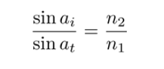
The process of refraction is described by Snell’s law, which defines the relationship between
the angle of incidence and the angle of refraction.

Snell’s law describes the angle of incidence (ai) as the angle between the incoming light
ray and the normal to the surface, and the angle of refraction (at) as the angle between the
transmitted ray and the extended normal. The material through which the incident light ray
travels and the material containing the transmitted light ray are each described by an index of
refraction (n1 and n2 in the figure). The ratio between the two indices of refraction defines the
amount that the light ray will be bent at the interface.
Starting with Snell’s law, and with a bit of mathematical effort, we can derive a formula for
the transmitted vector, given the ratio of the indices of refraction, the normal vector, and the
incoming vector.
However, there’s no real need to do so, because GLSL provides a built-in function for computing
this transmitted vector called refract. We’ll make use of that function within this example.
It is usually the case that for transparent objects, not all of the light is transmitted through the
surface. Some of the light is reflected. In this example, we’ll model that in a very simple way,
and at the end of this recipe we’ll discuss a more accurate representation.
Set up your OpenGL program to provide the vertex position in attribute location 0 and the
vertex normal in attribute location 1. As with the previous recipe, we’ll need to provide the
model matrix in the uniform variable ModelMatrix.
Load the cube map using the technique shown in the previous recipe. Place it in texture
unit zero.
Set the uniform variable WorldCameraPosition to the location of your viewer in world
coordinates. Set the value of the uniform variable Material.Eta to the ratio between the
index of refraction of the environment n1 and the index of refraction of the material n2
(n1/n2). Set the value of the uniform Material.ReflectionFactor to the fraction of
light that is reflected at the interface (a small value is probably what you want).
As with the preceding example, if you want to draw the environment, set the uniform
variable DrawSkyBox to true, then draw a large cube surrounding the scene, and then
set DrawSkyBox to false.
To render an object with reflection and refraction as well as the cube map itself, carry out the
following steps:
- Use the following code within the vertex shader:
layout (location = 0) in vec3 VertexPosition;
layout (location = 1) in vec3 VertexNormal;
out vec3 ReflectDir; // Reflected direction
out vec3 RefractDir; // Transmitted direction
struct MaterialInfo {
float Eta; // Ratio of indices of refraction
float ReflectionFactor; // Percentage of reflected light
};
uniform MaterialInfo Material;
uniform bool DrawSkyBox;
uniform vec3 WorldCameraPosition;
uniform mat4 ModelViewMatrix;
uniform mat4 ModelMatrix;
uniform mat3 NormalMatrix;
uniform mat4 ProjectionMatrix;
uniform mat4 MVP;
void main()
{
if( DrawSkyBox ) {
ReflectDir = VertexPosition;
} else {
vec3 worldPos = vec3( ModelMatrix *
vec4(VertexPosition,1.0) );
vec3 worldNorm = vec3(ModelMatrix *
vec4(VertexNormal, 0.0));
vec3 worldView = normalize( WorldCameraPosition –
worldPos );
ReflectDir = reflect(-worldView, worldNorm );
RefractDir = refract(-worldView, worldNorm,
Material.Eta );
}
gl_Position = MVP * vec4(VertexPosition,1.0);
}
- Use the following code within the fragment shader:
in vec3 ReflectDir;
in vec3 RefractDir;
layout(binding=0) uniform samplerCube CubeMapTex;
uniform bool DrawSkyBox;
struct MaterialInfo {
float Eta; // Ratio of indices of refraction
float ReflectionFactor; // Percentage of reflected light
};
uniform MaterialInfo Material;
layout( location = 0 ) out vec4 FragColor;
void main() {
// Access the cube map texture
vec4 reflectColor = texture(CubeMapTex, ReflectDir);
vec4 refractColor = texture(CubeMapTex, RefractDir);
if( DrawSkyBox )
FragColor = reflectColor;
else
FragColor = mix(refractColor, reflectColor,
Material.ReflectionFactor);
}
- In the render portion of the OpenGL program, set the uniform DrawSkyBox to true,
and then draw a cube surrounding the entire scene, centered at the origin. This
will become the sky box. Following that, set DrawSkyBox to false, and draw the
object(s) within the scene.
Both shaders are quite similar to the shaders in the previous recipe.
The vertex shader computes the position, normal, and view direction in world coordinates
(worldPos, worldNorm, and worldView). They are then used to compute the reflected
direction using the reflect function, and the result is stored in the output variable
ReflectDir. The transmitted direction is computed using the built-in function refract
(which requires the ratio of the indices of refraction Material.Eta). This function makes
use of Snell’s law to compute the direction of the transmitted vector which is then stored in
the output variable RefractDir.
In the fragment shader, we use the two vectors ReflectDir and RefractDir to access
the cube map texture. The color retrieved by the reflected ray is stored in reflectColor
and the color retrieved by the transmitted ray is stored in refractColor. We then mix those
two colors together based on the value of Material.ReflectionFactor. The result is a
mixture between the color of the reflected ray and the color of the transmitted ray.
The following image shows the teapot rendered with 10% reflection and 90% refraction.
(Cubemap © Paul Debevec.)
This technique has the same drawbacks that were discussed in the There’s more… section of
the preceding recipe, Simulating reflection with cube maps.
Like most real-time techniques, this is a simplification of the real physics of the situation.
There are a number of things about the technique that could be improved to provide more
realistic looking results.
The Fresnel equations
The amount of reflected light actually depends on the angle of incidence of the incoming
light. For example, when looking at the surface of a lake from the shore, much of the light
is reflected and it is easy to see reflections of the surrounding environment on the surface.
However, when floating on a boat on the surface of the lake and looking straight down, there
is less reflection and it is easier to see what lies below the surface. This effect is described by
the Fresnel equations (after Augustin-Jean Fresnel).
The Fresnel equations describe the amount of light that is reflected as a function of the angle
of incidence, the polarization of the light, and the ratio of the indices of refraction. If we ignore
the polarization, it is easy to incorporate the Fresnel equations into the preceding shaders. A
very good explanation of this can be found in the book The OpenGL Shading Language, 3rd
Edition, Randi J Rost, Addison-Wesley Professional, 2009.
Chromatic aberration
White light is of course composed of many different individual wavelengths (or colors). The
amount that a light ray is refracted is actually wavelength dependent. This causes the effect
where a spectrum of colors can be observed at the interface between materials. The most
well-known example of this is the rainbow that is produced by a prism.
We can model this effect by using slightly different values of Eta for the red, green, and blue
components of the light ray. We would store three different values for Eta, compute three
different reflection directions (red, green, and blue), and use those three directions to look up
colors in the cube map. We take the red component from the first color, the green component
from the second, and the blue component for the third, and combine the three components
together to create the final color for the fragment.
Refracting through both sides of the object
It is important to note that we have simplified things by only modeling the interaction of
the light with one of the boundaries of the object. In reality the light would be bent once
when entering the transparent object, and again when leaving the other side. However, this
simplification generally does not result in unrealistic looking results. As is often the case in
real-time graphics, we are more interested in a result that looks good than one that models
the physics accurately.


 82
82


 被折叠的 条评论
为什么被折叠?
被折叠的 条评论
为什么被折叠?
 到【灌水乐园】发言


