


 本文基于PX4开源软件框架,对比其与BetaFlight飞控代码的差异,介绍了PX4的两种模拟框架——SITL和HITL,前者飞控栈代码跑在PC上,后者跑在真实飞控硬件上。还提及了模拟器类型和MAVLink API软件接口,最后表示会在参考资料给出应用操作方法。
PX4模块设计之一:SITL & HITL模拟框架
基于PX4开源软件框架简明简介的框架设计,逐步分析内部模块功能设计。
PX4整个解决方案与BetaFlight飞控代码两者解决的问题是完全不一样的。为什么这么说,因为BetaFlight只是飞控代码,主要是用在飞控端(而且更多采用的是手动和FPV功能),应用领域大体是竞赛、穿越航拍等特殊场景;而PX4从设计上是一个定位专业级自动导航的系统。
1. 模拟框架
因此,PX4的设计上有两种模拟框架(Paparazzi也有类似模拟框架),用来模拟飞控在真实环境中的行为。
- Software In the Loop (SITL) simulation
- Hardware In the Loop (HITL) simulation
1.1 SITL模拟框架
Software In the Loop (SITL) simulation:飞控栈代码跑在PC上,然后通过UDP端口与模拟器相连,针对模拟器模拟的物理传感参数,进行飞控行为的仿真。

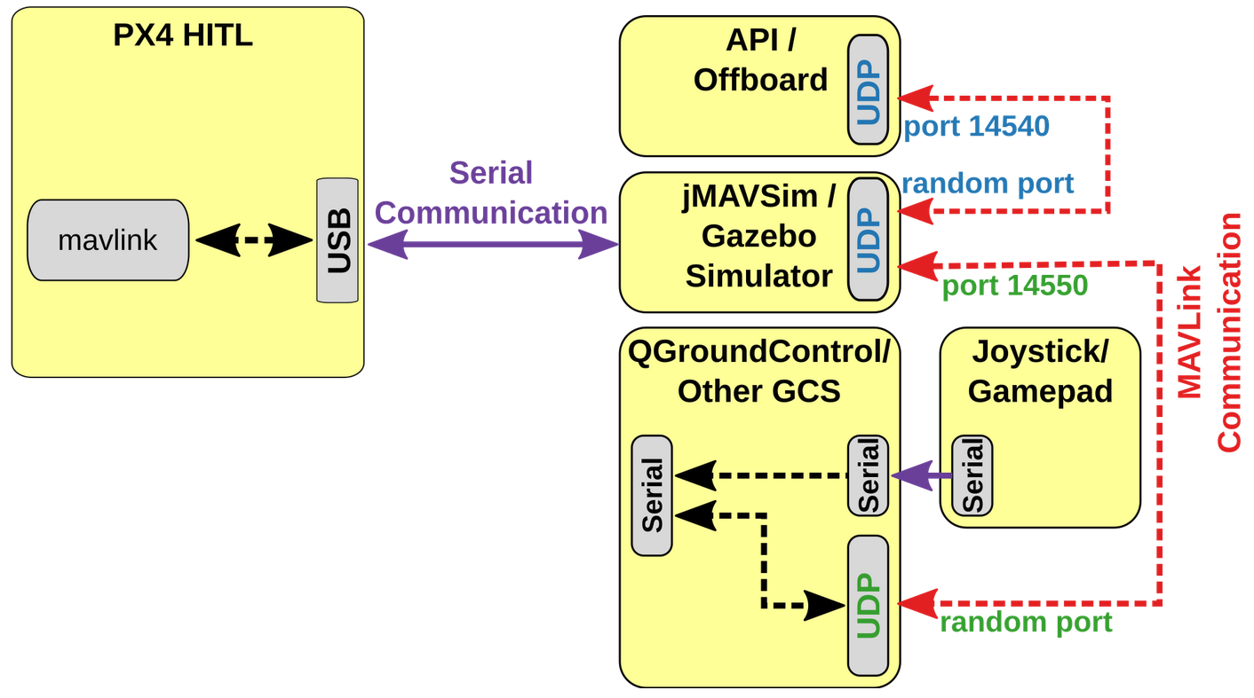
1.2 HITL模拟框架
Hardware In the Loop (HITL) simulation:飞控栈代码跑在真实飞控硬件上,然后通过USB端口与模拟器相连,根据模拟器模拟硬件传感数据,进行飞控行为的仿真。
2. 模拟器类型
模拟器的种类和支持机型详见下面列表:
| 模拟器 | 机型支持 |
|---|---|
| Gazebo | Quad (Iris and Solo, Hex (Typhoon H480), Generic quad delta VTOL, Tailsitter, Plane, Rover, Submarine |
| FlightGear | Plane, Autogyro, Rover |
| JSBSim | Plane, Quad, Hex |
| jMAVSim | Quad |
| AirSim | Iris (MultiRotor model and a configuration for PX4 QuadRotor in the X configuration). |
| Simulation-In-Hardware (SIH) | Plane, Quad, Tailsitter |
| Ignition Gazebo | Quad |
3. MAVLink API
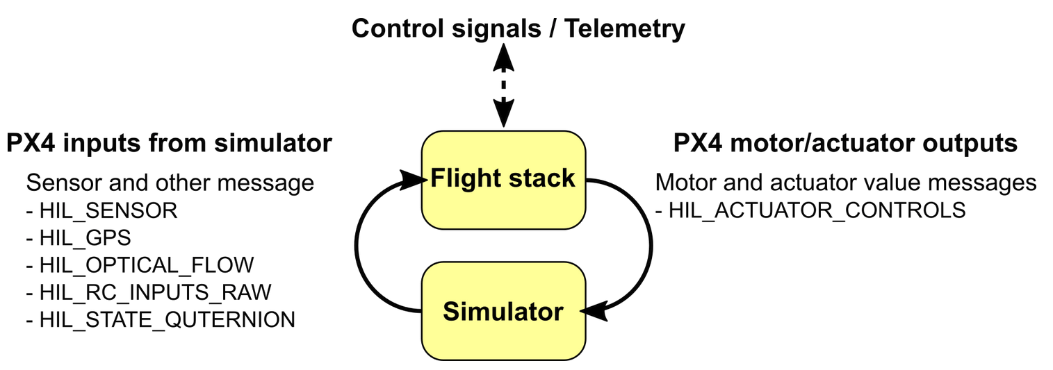
通过第1章节,可以看到连接Simulator和PX4飞控栈的是mavlink API软件接口。
| 消息 | 方向 | 描述 |
|---|---|---|
| HIL_ACTUATOR_CONTROLS | PX4 to Sim | PX4 control outputs (to motors, actuators). |
| HIL_SENSOR | Sim to PX4 | Simulated IMU readings in SI units in NED body frame. |
| HIL_GPS | Sim to PX4 | The simulated GPS RAW sensor value. |
| HIL_OPTICAL_FLOW | Sim to PX4 | Simulated optical flow from a flow sensor (e.g. PX4FLOW or optical mouse sensor) |
| HIL_STATE_QUATERNION | Sim to PX4 | Contains the actual “simulated” vehicle position, attitude, speed etc. This can be logged and compared to PX4’s estimates for analysis and debugging (for example, checking how well an estimator works for noisy (simulated) sensor inputs). |
| HIL_RC_INPUTS_RAW | Sim to PX4 | The RAW values of the RC channels received |
A SITL build of PX4 uses simulator_mavlink.cpp to handle these messages while a hardware build in HIL mode uses mavlink_receiver.cpp. Sensor data from the simulator is written to PX4 uORB topics. All motors / actuators are blocked, but internal software is fully operational.
4. 总结
关于具体如何应用这两种模拟场景,具体的操作命令、配置方法,在参考资料里面我们会给出,有兴趣的朋友可以再深入了解。
通过前面PX4开源软件框架简明简介和关于模拟仿真框架的讨论,期望能够从高维度设计层面思考,完整解决方案设计需要考虑的方方面面。
【1】Software In the Loop (SITL) simulation
【2】Hardware In the Loop (HITL) simulation


 1951
1951

 被折叠的 条评论
为什么被折叠?
被折叠的 条评论
为什么被折叠?
 到【灌水乐园】发言


