


 本文介绍了如何在Coppeliasim仿真环境中,通过ROS节点控制UR5机械臂,实现从脚本中定义的圆弧路径。作者展示了从修改脚本、添加dummy对象到建立ROS节点进行轨迹发布和接收的整个过程,并讨论了可能出现的问题和后续改进方向。
Coppeliasim仿真:ROS节点规划UR5画圆
紧接上节,本节我们写一个自己的小demo,重点在于ROS通讯在Coppeliasim中的应用
理解本篇需要对Coppeliasim的基本使用以及ROS有一定的了解
任务描述:通过ROS节点发布轨迹信息,Coppeliasim中订阅并执行机械臂画圆任务
总体控制思路分析
为简单起见,我们使用软件自带的UR5机械臂模型,将其拖入新的场景中
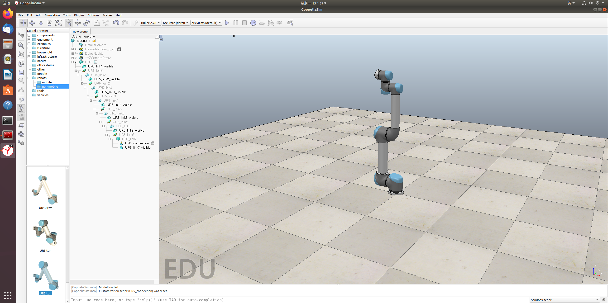
根据前文的介绍,有了基本的机器人模型后,我们还需要对其脚本进行编写配置,比如发布、订阅话题等。
观察发现这个模型原本就带有两个子脚本,我们重点关注其中的线程子脚本,打开其内容:
-- This is a threaded script, and is just an example!
function sysCall_threadmain()
    jointHandles={-1,-1,-1,-1,-1,-1}
    for i=1,6,1 do
        jointHandles[i]=sim.getObjectHandle('UR5_joint'..i)
    end

    -- Set-up some of the RML vectors:
    vel=180
    accel=40
    jerk=80
    currentVel={0,0,0,0,0,0,0}
    currentAccel={0,0,0,0,0,0,0}
    maxVel={vel*math.pi/180,vel*math.pi/180,vel*math.pi/180,vel*math.pi/180,vel*math.pi/180,vel*math.pi/180}
    maxAccel={accel*math.pi/180,accel*math.pi/180,accel*math.pi/180,accel*math.pi/180,accel*math.pi/180,accel*math.pi/180}
    maxJerk={jerk*math.pi/180,jerk*math.pi/180,jerk*math.pi/180,jerk*math.pi/180,jerk*math.pi/180,jerk*math.pi/180}
    targetVel={0,0,0,0,0,0}

    targetPos1={90*math.pi/180,90*math.pi/180,-90*math.pi/180,90*math.pi/180,90*math.pi/180,90*math.pi/180}
    sim.rmlMoveToJointPositions(jointHandles,-1,currentVel,currentAccel,maxVel,maxAccel,maxJerk,targetPos1,targetVel)

    targetPos2={-90*math.pi/180,45*math.pi/180,90*math.pi/180,135*math.pi/180,90*math.pi/180,90*math.pi/180}
    sim.rmlMoveToJointPositions(jointHandles,-1,currentVel,currentAccel,maxVel,maxAccel,maxJerk,targetPos2,targetVel)

    targetPos3={0,0,0,0,0,0}
    sim.rmlMoveToJointPositions(jointHandles,-1,currentVel,currentAccel,maxVel,maxAccel,maxJerk,targetPos3,targetVel)
end
这个脚本的内容比较简单:它在关节空间设定了三个点,然后直接控制机械臂依次到达这三个点
点击运行发现机器人实际工作和脚本内容吻合
既然这个脚本能够工作,那我们为了让机械臂画圆,能不能在这个脚本的基础上进行修改呢?
即通过给定画一个圆的多个点,让机械臂依此经过。
这个思路很好,但是关节空间的点位我们很难得到,或者说很难描述。
对我们人来说,在笛卡尔空间进行规划会更直观。
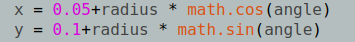
也就是说,我们现在的目的转换为描述一个圆上的多个点,将其发布给机器人执行,这里我给出一个平面上圆的描述
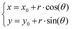
基于这个公式,选定一个固定高度z,那么空间中的点(x, y, z)就很容易得到了,将这些点作为一个话题发布给软件,软件直接执行即可。
为实现这个目标,接下来我们首先搭建一个可以以这种方式工作的机器人平台进行思路的验证。
Coppeliasim中的执行平台搭建
上文中的函数sim.rmlMoveToJointPositions不满足我们的需求,因此我们打开帮助文档,发现如下:
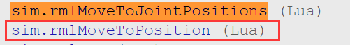
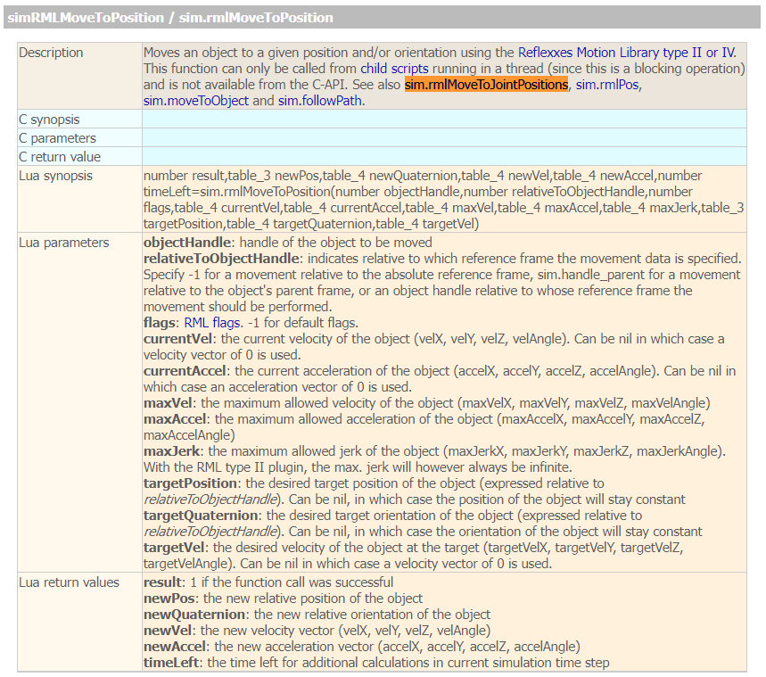
这个函数就是我们需要的了,sim.rmlMoveToPosition:通过接收table_3 targetPosition,执行运动。
为了使用这个函数,我们在场景中添加两个dummy,如下:
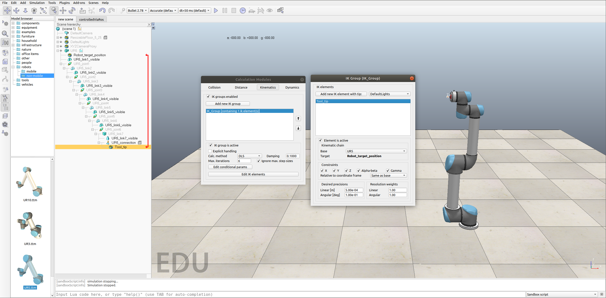
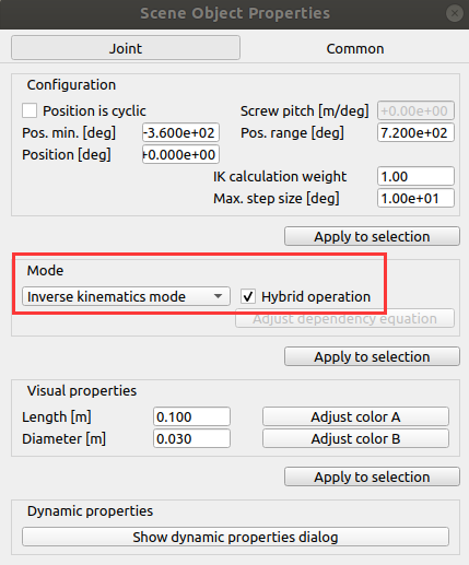
修改机器人六个关节的Mode为:
然后,替换线程子脚本:
function sysCall_threadmain()
    robotHandle = sim.getObjectHandle('UR5')
    targetHandle = sim.getObjectHandle('Robot_target_position')
    moveRobotToCartesianCircle(robotHandle, targetHandle)
end

function moveRobotToCartesianCircle(robotHandle, targetHandle)
    radius = 0.2
    height = 0.6
    steps = 100

    -- 这些约束是我随便给的
    local currentVel={0,0,0,0}
    local currentAccel={0,0,0,0}
    local maxVel={0.08,0.08,0.08,0.08}
    local maxAccel={0.1,0.1,0.1,0.1}
    local maxJerk={0.1,0.1,0.,0.1}
    local targetPosition={0.2,0.2,0.5}
    -- targetQuaternion = ...
    local targetVel={0,0,0,0}

    for i = 0, steps do
        angle = 2 * math.pi * i / steps
        x = 0.05+radius * math.cos(angle)
        y = 0.1+radius * math.sin(angle)
        --print(angle)

        -- Get the transformation matrix of the robot's base
        baseMatrix = sim.getObjectMatrix(robotHandle, -1)

        -- Transform the Cartesian coordinates to the robot's base local coordinates
        localCoords = sim.multiplyVector(baseMatrix, {x, y, height})

        -- Set the target position in the robot's base local coordinates
        sim.setObjectPosition(targetHandle, robotHandle, localCoords)
        if i <= 3 then
            sim.wait(3)
        end
        print("set ok")

        -- Move the robot to the target position
        sim.rmlMoveToPosition(targetHandle,-1,-1,currentVel,currentAccel,maxVel,maxAccel,maxJerk,nil,nil,targetVel)
        print("move ok")
        sim.wait(0.05)

        print(i,   steps)
    end
end
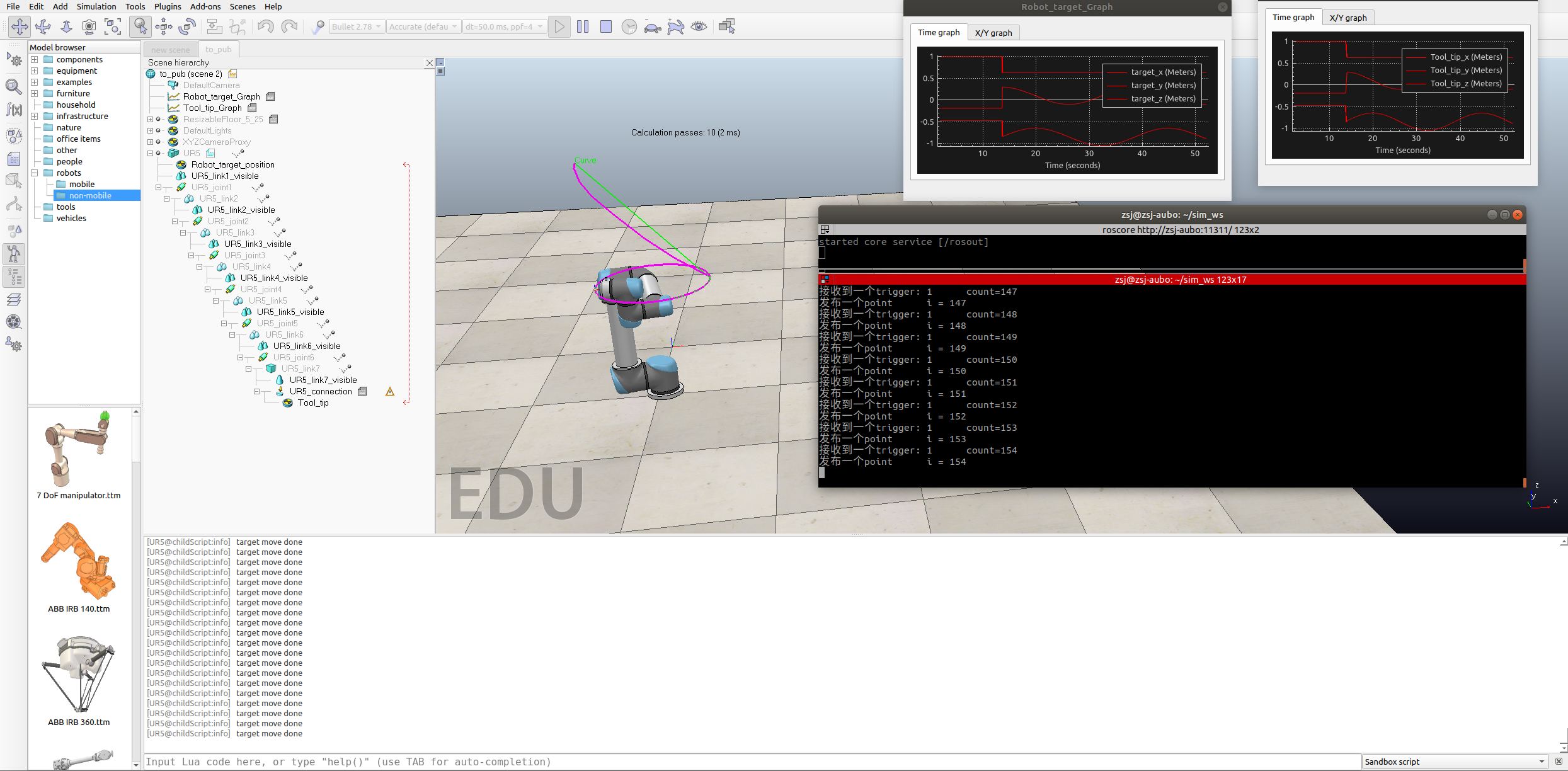
为了便于大家观察,我又添加了两个Graph用于展示三维的曲线,点击运行,有结果如下:
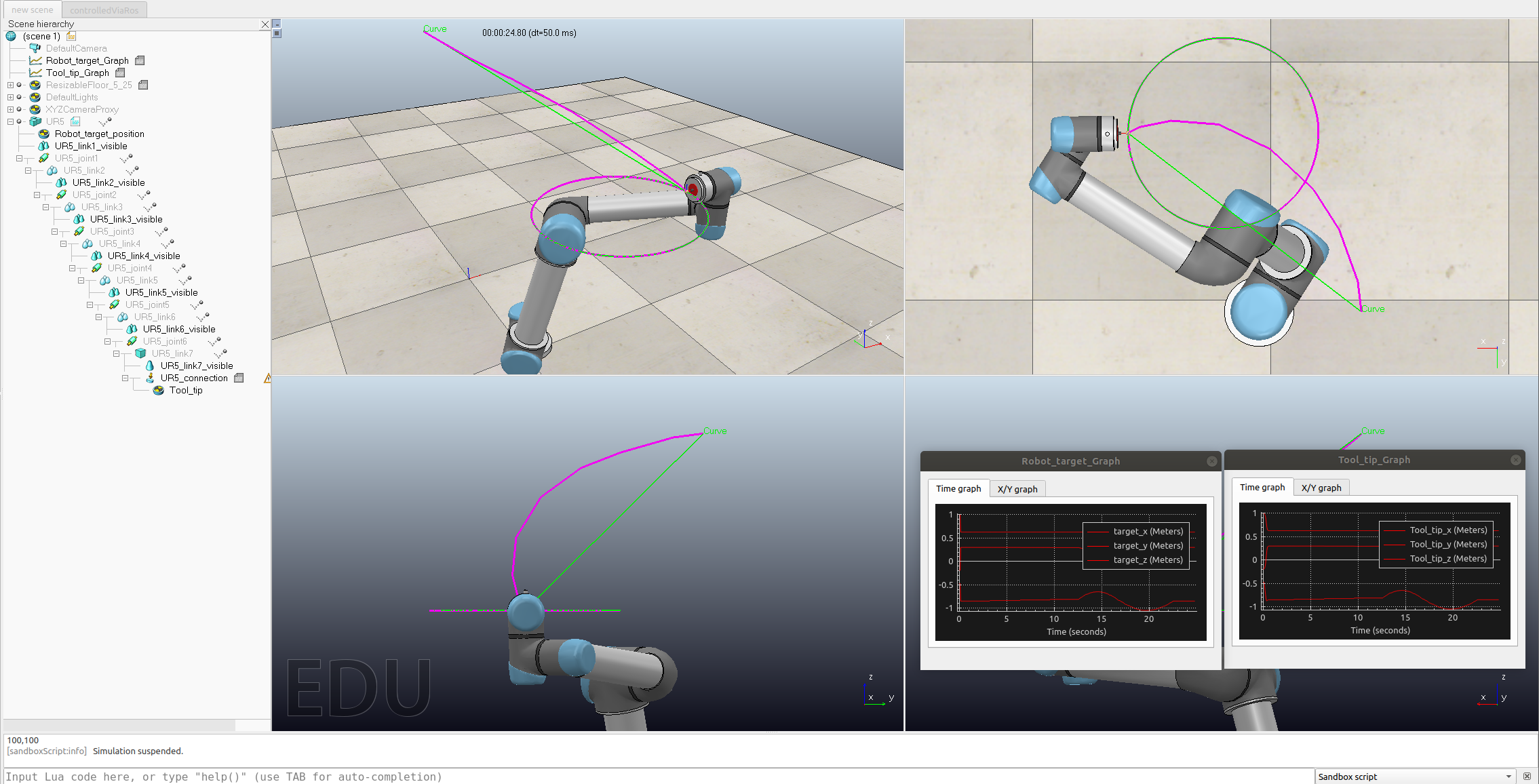
其中,绿色是Robot_target_position的轨迹
紫色是Tool_tip的轨迹
可见这个圆画得还是很漂亮的。
关于为什么要用dummy,以及为什么两条轨迹会有部分不重合,这属于Coppeliasim软件的工作机制问题
至此,我们完成了基本的执行平台的搭建,接下来使用ROS节点发布上面程序中的关键点信息。
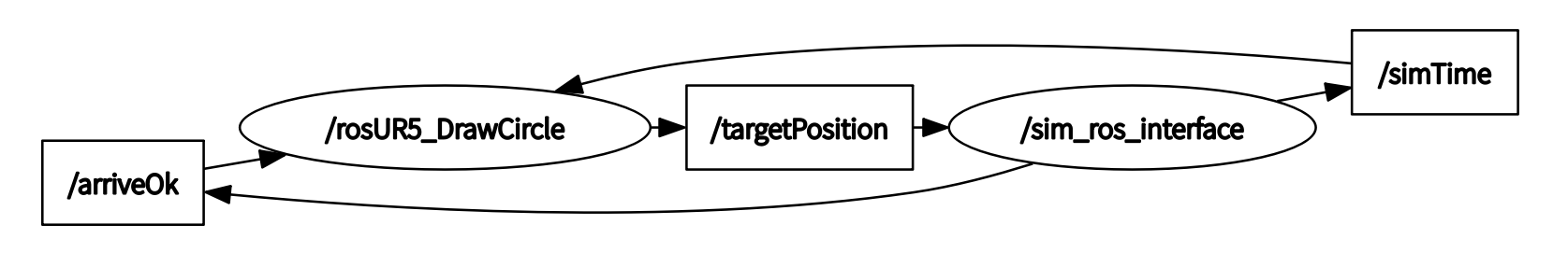
ROS节点与Coppeliasim通讯
我们有两个节点,一个是/sim_ros_interface,一个是/rosUR5_DrawCircle
其中,/sim_ros_interface订阅轨迹点,rosUR5_DrawCircle发布轨迹点
rosUR5_DrawCircle是我们自己编写的
我们模仿前一篇文章的内容,在coppeliasim中编写新的脚本替换上面的线程子脚本的内容:
function getTransformStamped(objHandle,name,relTo,relToName)
    t=sim.getSystemTime()
    p=sim.getObjectPosition(objHandle,relTo)
    o=sim.getObjectQuaternion(objHandle,relTo)
    return {
        header={
            stamp=t,
            frame_id=relToName
        },
        child_frame_id=name,
        transform={
            translation={x=p[1],y=p[2],z=p[3]},
            rotation={x=o[1],y=o[2],z=o[3],w=o[4]}
        }
    }
end


function rosNodeInit()
    robotHandle = sim.getObjectHandle('UR5')
    targetHandle = sim.getObjectHandle('Robot_target_position')

    if simROS then
        sim.addLog(sim.verbosity_scriptinfos, "ROS interface was found")

        local robotPositionTopicName = "targetPosition" -- for subscribe
        local arriveOkTopicName = 'arriveOk' -- for publish
        local simulationTimeTopicName = 'simTime' -- for publish

        simTimePub=simROS.advertise('/'..simulationTimeTopicName,'std_msgs/Float32')
        arrivePositionPub = simROS.advertise('/'..arriveOkTopicName,'std_msgs/Bool')
        robotPositionSub = simROS.subscribe('/'..robotPositionTopicName,'geometry_msgs/Point32','robotPosition_cb')

        sim.addLog(sim.verbosity_scriptinfos, "publisher and subscriber create succesed")
    else
        sim.addLog(sim.verbosity_scripterrors,"ROS interface was not found. Cannot run.")
    end
end


function controlRobotViaROS(robotHandle, targetHandle)
    while(true)
    do
        if triggerNextPointFlag == true and connectFlag == true then
            local pointTrigger={}
            pointTrigger['data']=true
            simROS.publish(arrivePositionPub, pointTrigger)
            triggerNextPointFlag = false
        elseif connectFlag == false then
            local pointTrigger={}
            pointTrigger['data']=true
            simROS.publish(arrivePositionPub, pointTrigger)
        end
        simROS.publish(simTimePub, {data=sim.getSimulationTime()})
        simROS.sendTransform(getTransformStamped(robotHandle,'rosInterfaceControlledBubbleRob',-1,'world'))
        sim.wait(0.2)
    end
end


function sysCall_threadmain()
    triggerNextPointFlag = true
    connectFlag = false
    rosNodeInit()
    controlRobotViaROS(robotHandle, targetHandle)
end


function robotPosition_cb(msg)
    local currentVel={0,0,0,0}
    local currentAccel={0,0,0,0}
    local maxVel={0.08,0.08,0.08,0.08}
    local maxAccel={0.1,0.1,0.1,0.1}
    local maxJerk={0.1,0.1,0.,0.1}
    local targetPosition={0.2,0.2,0.5}
    -- targetQuaternion = ...
    local targetVel={0,0,0,0}

    baseMatrix = sim.getObjectMatrix(robotHandle, -1)
    localCoords = sim.multiplyVector(baseMatrix, {msg.x, msg.y, msg.z})
    sim.setObjectPosition(targetHandle, robotHandle, localCoords)

    sim.rmlMoveToPosition(targetHandle,-1,-1,currentVel,currentAccel,maxVel,maxAccel,maxJerk,nil,nil,targetVel)
    sim.addLog(sim.verbosity_scriptinfos, "target move done")
    triggerNextPointFlag = true
    connectFlag = true
end
然后,编写新的ROS节点,节点代码如下:
#include "ros/ros.h"
#include "std_msgs/Bool.h"
#include "std_msgs/Float32.h"
#include "geometry_msgs/Point32.h"

bool arriveTrigger=false;
struct timeval tv;
unsigned int currentTime_updatedByTopicSubscriber=0; /* 记录订阅接收到到ROS消息的时间 */
float simulationTime=0.0; /* 记录coppeliasim上的时间 */
int count = 0;

void arriveOkCallback(const std_msgs::Bool& arriveTrigger_msg)
{
    if (gettimeofday(&tv,NULL)==0)
        currentTime_updatedByTopicSubscriber=tv.tv_sec;
    arriveTrigger = arriveTrigger_msg.data; /* 对面只会发布true */
    count++;
    printf("接收到一个trigger: %d      count=%d\n", arriveTrigger,count);
}

void simulationTimeCallback(const std_msgs::Float32& simTime)
{
    simulationTime=simTime.data;; /* 这里没用上这个参数 */
}

int main(int argc, char *argv[])
{
    std::string robotPositionTopic;
    std::string arriveOkTopic;
    std::string simulationTimeTopic;
    if(argc>=4)
    {
        robotPositionTopic = argv[1];
        arriveOkTopic = argv[2];
        simulationTimeTopic = argv[3];

        robotPositionTopic = "/"+robotPositionTopic;
        arriveOkTopic = "/"+arriveOkTopic;
        simulationTimeTopic = "/"+simulationTimeTopic;
    }
    else
    {
        printf("Indicate following arguments: 'robotPositionTopic arriveOkTopic simulationTimeTopic'!\n");
        sleep(5000);
        return 0;
    }

    int _argc = 0;
    char **_argv = NULL;

    std::string nodeName("rosUR5_DrawCircle");
    ros::init(_argc, _argv, nodeName.c_str());

    if(!ros::master::check())
        return(0);

    ros::NodeHandle n;

    printf("positionControl just started with node name %s\n", nodeName.c_str());

    ros::Subscriber subArriveOk = n.subscribe(arriveOkTopic.c_str(), 1, arriveOkCallback);
    ros::Subscriber subSimulation = n.subscribe(simulationTimeTopic.c_str(), 1, simulationTimeCallback);

    ros::Publisher pubRobotPosition = n.advertise<geometry_msgs::Point32>(robotPositionTopic.c_str(), 1);

    float driveBackStartTime=-99.0f;
    unsigned int currentTime; /* 节点本地的时间 */
    if (gettimeofday(&tv,NULL)==0)
    {
        currentTime_updatedByTopicSubscriber=tv.tv_sec;
        currentTime=currentTime_updatedByTopicSubscriber;
    }

    float radius = 0.2;
    float height = 0.6;
    float steps = 100;
    int i = 0; /* 用于控制点生成 */

    while(ros::ok)
    {
        if (gettimeofday(&tv,NULL)==0)
        {
            currentTime=tv.tv_sec; /* 当前时间的整数部分 */
            if (currentTime-currentTime_updatedByTopicSubscriber>9)
            {
                printf("we didn't receive any arrive trigger information for quite a while... we leave");
                break;
            }
        }

        if(arriveTrigger == true)
        {
            geometry_msgs::Point32 pointToSend;

            i++;

            float angle = 2 * M_PI * i / steps;
            float x = 0.05 + radius * cos(angle);
            float y = 0.1 + radius * sin(angle);
            float z = height;

            pointToSend.x = x;
            pointToSend.y = y;
            pointToSend.z = z;
            pubRobotPosition.publish(pointToSend);
            printf("发布一个point      i = %d\n", i);

            arriveTrigger = false;
        }

        ros::spinOnce();
        usleep(5000);
    }

    ros::shutdown();
    printf("positionControl just ended!\n");
    return 0;
}
至此,编程工作基本完成。
首先点击coppeliasim场景中的运行按钮,然后在终端中rosrun
rosrun rosPositionControl PositionControl /targetPosition /arriveOk /simTime
即可实现功能
小结
至此,我们实现了由ROS节点向coppeliasim发送位置点进行控制的小demo,程序比较简单,主要是通过模仿官方案例的写法打通了控制的流程。
但是有一点要注意,在我的测试中,上面的程序会出现意外的错误,即
我简单调试了,但暂时没有找到原因,欢迎大家一起debug!
欢迎大家讨论,共同进步。


 2260
2260

 被折叠的 条评论
为什么被折叠?
被折叠的 条评论
为什么被折叠?
 到【灌水乐园】发言


