


文章目录
- 一、ld06 激光雷达简介
- 1.1 DTOF 激光雷达测距原理
- 1.2 产品特性
- 1.3 功能介绍
- 1.3.1. 360°扫描测距
- 1.3.2. PWM 控速
- 1.3.3. 玻璃检测
- 1.4 技术参数
- 1.4.1 性能参数
- 1.4.1 电气与机械参数
- 1.4.1 光学参数
- 1.5 其他参数
- 1.5.1 通讯接口
- 1.5.1 坐标系定义
- 二、ROS2 驱动
- 2.1. 下载 ROS2 驱动
- 2.2 系统设置
- 2.3 编译
- 2.4 运行
- 2.4.1 设置环境变量
- 2.4.2 启动激光雷达节点
- 三、ROS2 节点数据分析
- 2.1 查看点云数据类型
- 2.1.1 查看话题
- 2.1.2 查看点云话题信息
- 2.1.3 查看点云数据类型
一、ld06 激光雷达简介
1.1 DTOF 激光雷达测距原理
STL-06P 主要由激光测距核心,无线传电单元,无线通讯单元,角度测量单元、电机驱动单元和机械外壳组成。
STL-06P 测距核心采用 DTOF 技术,可进行每秒 5000 次的测距。每次测距时,雷达发射出红外激光,激光遇到目标物体后被反射到单光子接收单元。由此,我们获取到了激光的发出时间和单光子接收单元收到激光的时间,两者的时间差即光的飞行时间,飞行时间再结合光速即可解算出距离。获取到距离数据后,会融合角度测量单元测量到的角度值组成点云数据,然后内部通过无线通讯将点云数据发送到外部接口。同时外部接口支持 PWM 输入,使电机驱动单元驱动电机转动。外部控制单元获取到转速后,通过 PID 算法闭环控制到指定的转速,从而使雷达稳定工作。
STL-06P 点云数据形成的环境扫描图意图如下:
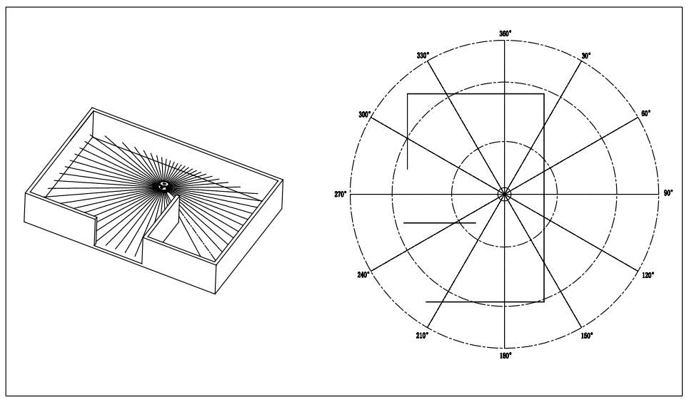
该产品主要适用于机器人(比如扫地机器人、服务机器人等)的导航及避障,通过进行 360° 全方位扫描室内布局,建立地图,规划出行走路径。同时也适用于机器人教育研究等。
1.2 产品特性
STL-06P 激光雷达主要特性:
➢ 近距离高测距精度,0.03~0.5m 距离内的均值误差在±10mm 以内;
➢ 极致小尺寸,易于集成设计,保证客户产品的美观性;
➢ 抗环境光干扰能力强,满足 60Klux 环境使用;
➢ 支持玻璃墙检测;
➢ 性能稳定,寿命高达 10000 小时;
1.3 功能介绍
1.3.1. 360°扫描测距
STL-06P 激光雷达默认按照 10Hz 转速扫描,并以每秒 5000 次的频率进行测距。通过 UART 接口输出周围 360°环境的测距信息(包含距离和角度数据)。
1.3.2. PWM 控速
STL-06P 具有可无级调速的电机驱动器,支持内部控速和外部控速。在 PWM引脚接地时,默认为内部调速,默认转速为 10Hz。外部控速需要在 PWM 引脚接入方波信号,可通过 PWM 信号占空比控制电机的启、停和转速。由于每个产品电机的个体差异,占空比设置为典型值时实际转速可能会有差异,如要精确控制电机转速,需根据接收数据中的转速信息进行闭环控制。
注:不使用外部控速时,必须将 PWM 引脚接地。
1.3.3. 玻璃检测
STL-06P 通过多回波检测技术,支持玻璃墙检测(入射角和法线的夹角在±5°以内),减少机器人运行过程中的碰撞,延长整机使用寿命,提高用户体验。
1.4 技术参数
1.4.1 性能参数


1.4.1 电气与机械参数

1.4.1 光学参数

1.5 其他参数
1.5.1 通讯接口

1.5.1 坐标系定义

二、ROS2 驱动
2.1. 下载 ROS2 驱动
cd ~

mkdir -p ldlidar_ros2_ws/src

cd ldlidar_ros2_ws/src

git clone  https://github.com/ldrobotSensorTeam/ldlidar_stl_ros2.git
2.2 系统设置
第一步,通过板载串口或者USB转串口模块(例如,cp2102模块)的方式使雷达连接到你的系统主板.
第二步,设置雷达在系统中挂载的串口设备-x权限(以/dev/ttyUSB0为例)
实际使用时,根据雷达在你的系统中的实际挂载情况来设置,可以使用ls -l /dev命令查看.
cd ~/ldlidar_ros2_ws

sudo chmod 777 /dev/ttyUSB0
第三步,修改launch/目录下雷达产品型号对应的lanuch文件中的port_name值,以ld06.launch.py 和 /dev/ttyUSB0为例,如下所示.
#!/usr/bin/env python3
from launch import LaunchDescription
from launch_ros.actions import Node

'''
Parameter Description:
---
- Set laser scan directon:
  1. Set counterclockwise, example: {'laser_scan_dir': True}
  2. Set clockwise,        example: {'laser_scan_dir': False}
- Angle crop setting, Mask data within the set angle range:
  1. Enable angle crop fuction:
    1.1. enable angle crop,  example: {'enable_angle_crop_func': True}
    1.2. disable angle crop, example: {'enable_angle_crop_func': False}
  2. Angle cropping interval setting:
  - The distance and intensity data within the set angle range will be set to 0.
  - angle >= 'angle_crop_min' and angle <= 'angle_crop_max' which is [angle_crop_min, angle_crop_max], unit is degress.
    example:
      {'angle_crop_min': 135.0}
      {'angle_crop_max': 225.0}
      which is [135.0, 225.0], angle unit is degress.
'''

def generate_launch_description():
  # LDROBOT LiDAR publisher node
  ldlidar_node = Node(
      package='ldlidar_stl_ros2',
      executable='ldlidar_stl_ros2_node',
      name='LD06',
      output='screen',
      parameters=[
        {'product_name': 'LDLiDAR_LD06'},
        {'topic_name': 'scan'},
        {'frame_id': 'base_laser'},
        {'port_name': '/dev/ttyUSB0'},
        {'port_baudrate': 230400},
        {'laser_scan_dir': True},
        {'enable_angle_crop_func': False},
        {'angle_crop_min': 135.0},
        {'angle_crop_max': 225.0}
      ]
  )

  # base_link to base_laser tf node
  base_link_to_laser_tf_node = Node(
    package='tf2_ros',
    executable='static_transform_publisher',
    name='base_link_to_base_laser_ld06',
    arguments=['0','0','0.18','0','0','0','base_link','base_laser']
  )


  # Define LaunchDescription variable
  ld = LaunchDescription()

  ld.add_action(ldlidar_node)
  ld.add_action(base_link_to_laser_tf_node)

  return ld
2.3 编译
使用colcon编译.
cd ~/ldlidar_ros2_ws

colcon build
2.4 运行
2.4.1 设置环境变量
编译完成后需要将编译生成的相关文件加入环境变量,便于 ROS 环境可以识别, 执行命令如下所示, 该命令是临时给终端加入环境变量,意味着您如果重新打开新的终端,也需要重新执行如下命令.
cd ~/ldlidar_ros2_ws

source install/setup.bash
为了重新打开终端后,永久不用执行上述添加环境变量的命令,可以进行如下操作.
echo source ~/ldlidar_ros2_ws/install/setup.bash >> ~/.bashrc

source ~/.bashrc
2.4.2 启动激光雷达节点
产品型号为 LDROBOT LiDAR LD06
启动ld06 lidar node:
ros2 launch ldlidar_stl_ros2 ld06.launch.py
启动ld06 lidar node并显示激光数据在Rviz2上:
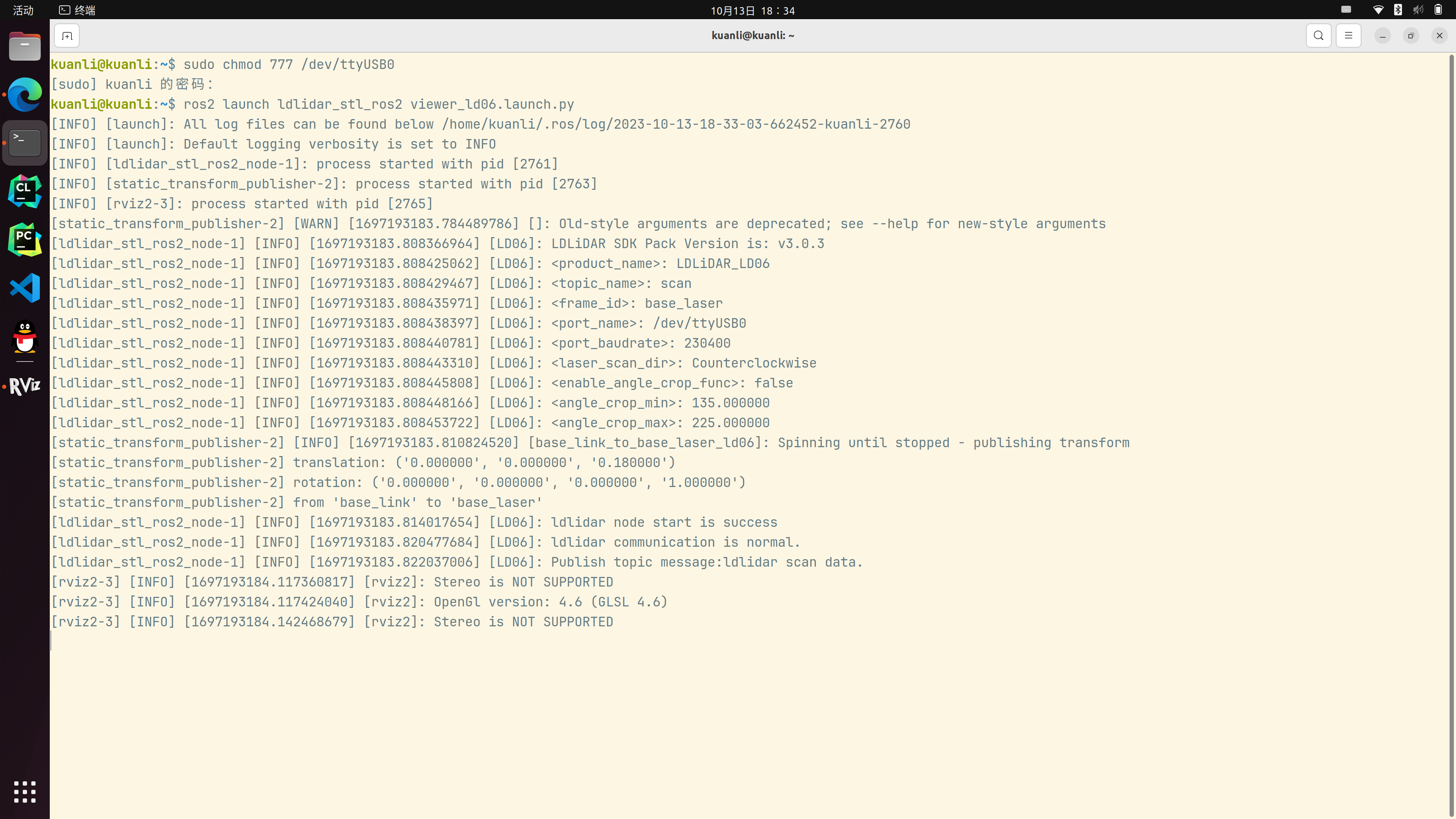
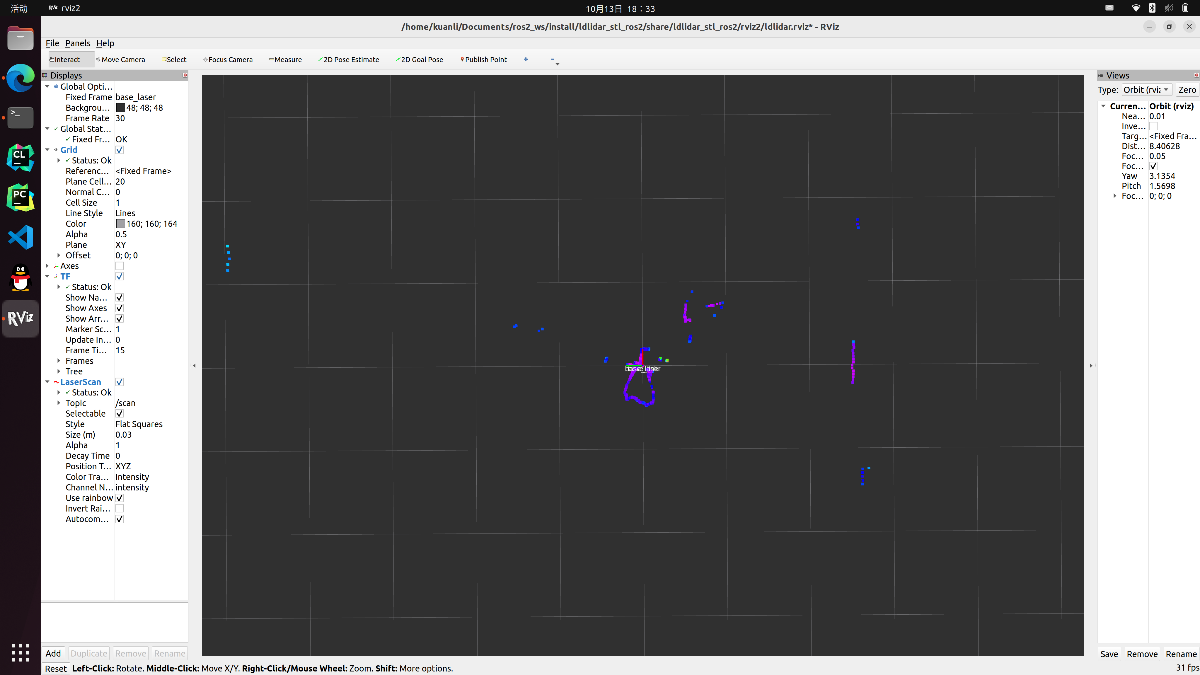
ros2 launch ldlidar_stl_ros2 viewer_ld06.launch.py
三、ROS2 节点数据分析
2.1 查看点云数据类型
2.1.1 查看话题
ros2 topic list
/clicked_point
/goal_pose
/initialpose
/parameter_events
/rosout
/scan
/tf
/tf_static
2.1.2 查看点云话题信息
ros2 topic info /scan
Type: sensor_msgs/msg/LaserScan
Publisher count: 1
Subscription count: 1
2.1.3 查看点云数据类型
ros2 interface show sensor_msgs/msg/LaserScan
# Single scan from a planar laser range-finder
#
# If you have another ranging device with different behavior (e.g. a sonar
# array), please find or create a different message, since applications
# will make fairly laser-specific assumptions about this data

std_msgs/Header header # timestamp in the header is the acquisition time of
	builtin_interfaces/Time stamp
		int32 sec
		uint32 nanosec
	string frame_id
                             # the first ray in the scan.
                             #
                             # in frame frame_id, angles are measured around
                             # the positive Z axis (counterclockwise, if Z is up)
                             # with zero angle being forward along the x axis

float32 angle_min            # start angle of the scan [rad]
float32 angle_max            # end angle of the scan [rad]
float32 angle_increment      # angular distance between measurements [rad]

float32 time_increment       # time between measurements [seconds] - if your scanner
                             # is moving, this will be used in interpolating position
                             # of 3d points
float32 scan_time            # time between scans [seconds]

float32 range_min            # minimum range value [m]
float32 range_max            # maximum range value [m]

float32[] ranges             # range data [m]
                             # (Note: values < range_min or > range_max should be discarded)
float32[] intensities        # intensity data [device-specific units].  If your
                             # device does not provide intensities, please leave
                             # the array empty.


 991
991


 被折叠的 条评论
为什么被折叠?
被折叠的 条评论
为什么被折叠?
 到【灌水乐园】发言


