


 本文介绍了如何在Gazebo中构建复杂的环境模型,包括添加简单形状、从模型数据库导入模型、修改场景属性及物理特性等内容。教程还详细说明了如何使用数字高程模型创建逼真的地形,并提供了创建建筑群的步骤。
環境模型構建可以通過向其中添加模型實現,待之後補充,比較有趣的是建築物模型,
可以編輯多層樓層和房間,加入樓梯,窗戶和牆壁等,具體可以參考附錄,等有空再補充。
起伏地形環境構建可以參考之前內容:在Gazebo中使用DEM構建起伏地形環境
附錄:官方文檔
Building a world
This tutorial describes the process of creating a world with both static and dynamic objects.
Terminology
- World: The term used to describe a collection of robots and objects (such as buildings, tables, and lights), and global parameters including the sky, ambient light, and physics properties.
- Static: Entities marked as static (those having the
<static>true</static>element in SDF), are objects which only have collision geometry. All objects which are not meant to move should be marked as static, which is a performance enhancement. - Dynamic: Entities marked as dynamic (either missing the
<static>element or setting false in SDF), are objects which have both inertia and a collision geometry.
Setup
Make sure Gazebo is installed.
Create a working directory for this tutorial:
$ mkdir ~/build_world_tutorial; cd ~/build_world_tutorialStart up gazebo, and you should see a world with just a ground plane.
$ gazebo
![]()
Adding Objects
Gazebo provides two mechanisms for adding objects to Gazebo.
- The first is a set of simple shapes, located above the render window.
![]()
- The second is via the model database, which is accessible by selecting the
Inserttab in the upper left corner.
![]()
Adding Simple Shapes
Boxes, spheres, and cylinders may be added to the world by clicking on the appropriate icon above the render window. Each shape is of unit size:
- Box: 1x1x1 meter
- Sphere: 1 meter diameter
- Cylinder: 1 meter diameter, 1 meter length
Select the box icon, and then move your mouse onto the render window. You will see a box that moves with your mouse. Left click when you are happy with the position of the box.
Repeat the same procedure for the sphere and cylinder. You should end with a world similar to this:

Adding Model from the Model Database
Gazebo's model database is a repository of all types of models including robots, tables, and building.
Select the
Inserttab in the upper left hand corner to access the model database.The list of models are divided into sections according to there current location. Each section is labeled with a path or URI. Selecting an object located on a remote server will cause the model to be downloaded and stored in
~/.gazebo/models.Try adding various models to the world. Be patient when downloading models, as some may be large.
You should end up with something similar to the following, depending on the models you decided to add:
![]()
Position Models
The pose of each model may be altered through the translate and rotate tools:
![]()
Translation
The translate tools allows you to move the object along the x, y, and z axes. Select this tool now and click on the object you want to move. A three axes visual marker will appear over the object, which allows you to move the object in x, y, and z directions.
You can also just click on the object itself and drag it to move on the x-y plane. You may control which axis the object moves along by pressing and holding the x, y, or z key while dragging the object.
Try moving the objects around now into a different configuration.
Rotation
The rotate tool allows you to orient a model around the x, y, and z axes. Select this tool now and click on the object you want to move. Three ring-shaped visual marker will appear over the object, which allows you to rotate the object around the x, y, and z axes.
Try rotating the objects into a different configuration.
Scale
The scale tool allows you to resize a model in the x, y, and z directions. Currently the scale tool only works with simple shapes, i.e. box, cylinder and sphere. Select this tool now and click on a simple shape. A three axes visual marker will appear over the object, which allows you to scale the x, y, and z dimensions of the object.
Try scaling the simple shapes into different sizes.
Delete Models
Model may also be deleted by selecting them and the hitting the Delete key, or by right-clicking on a model and selecting Delete.
Try deleting a few models.
Saving a World.
Once you are happy with a world it can be save through the File menu.
Select the File menu now, and choose Save As.
A pop-up will appear asking you to enter a new filename. Enter my_world.sdf and click okay.
Loading a World
A saved world may be loaded on the command line:
gazebo my_world.sdf
The filename must be in the current working directory, or you must specify the complete path.
Next
Modifying a world
This tutorial describes how to modify global properties including scene and physics properties.
Start gazebo:
$ gazebo
Scene Properties
In the World tab, select the scene item. A list of scene properties will be displayed in the list box below. Click the triangle to expand the properties.


These properties allow you to change the ambient light. Note: The background color will not change if the Sky is enabled.
Physics Properties
In the World tab, select the physics item. A list of physics properties will be displayed in the list box below.
- The
enable physicscheck-box can be used to disable physics while allowing plugins and sensors to continue running. - The
real time update rateparameter specifies in Hz the number of physics updates that will be attempted per second. If this number is set to zero, it will run as fast as it can. Note that the product ofreal time update rateandmax step sizerepresents the targetreal time factor, or ratio of simulation time to real-time. - The
max step sizespecifies the time duration in seconds of each physics update step.
In the gravity block:
- The
x,yandzparameters set the global gravity vector components in m/s^2.
In the solver block:
- The
iterationsparameter specifies the number of iterations to use for iterative LCP solvers (used by ODE and bullet). - The
SORparameter stands for successive over-relaxation, which can be used to try to speed the convergence of the iterative method.
The constraints block contains several parameters related to solving constraints:
- The
CFMandERPparameters stands for Constraint Force Mixing and Error Reduction Parameter and are used by ODE and bullet. The CFM and ERP parameters can be related to linear stiffness and damping coefficients. Themax velocityandsurface layerparameters are used to resolve contacts with a split impulse method. Any contacts with that penetrate deeper than a depth specified bysurface layerand have a normal velocity less thanmax velocitywill not bounce.
See the sdf physics documentation for a description of these parameters.

Next
Digital Elevation Models
Overview
A Digital Elevation Model (DEM) is a 3D representation of a terrain's surface that does not include any objects like buildings or vegetation. DEMs are frequently created by using a combination of sensors, such as LIDAR, radar, or cameras. The terrain elevations for ground positions are sampled at regularly-spaced horizontal intervals. Wikipedia is a good resource for getting more details about DEMs.
The term DEM is just a generic denomination, not a specific format. In fact, the DEMs can be represented as a grid of elevations (raster) or as a vector-based triangular irregular network (TIN). Currently, Gazebo only supports raster data in the supported formats available in GDAL.
The main motivation to support DEMs in Gazebo is to be able to simulate a realistic terrain. Rescue or agriculture applications might be interested in testing their robot behaviors using a simulated terrain that matches the real world.
Bring DEM support to Gazebo
In order to work with DEM files you should install GDAL libraries.
$ sudo apt-get install gdal-bin libgdal-dev libgdal1h python-gdal
DEM file and the definition into SDF format
There are several organizations that provide elevation data. As an example,let's download a DEM file of Mount St. Helensbeforeorafterits eruption back in the '80s. These files are in public domain and aredistributed by USGS.
Unzip the file and rename it mtsthelens.dem as follows:
cd ~/Downloads
wget https://bitbucket.org/osrf/gazebo_tutorials/raw/default/dem/files/mtsthelens_before.zip
unzip ~/Downloads/mtsthelens_before.zip -d /tmp
mv /tmp/30.1.1.1282760.dem /tmp/mtsthelens.dem
Usually, DEM files have big resolutions and Gazebo cannot handle it, so it's a good idea to adjust the resolution of your DEM. The next command will scale the terrain to 129x129 and will copy into the Gazebo media/dem/ directory.
$ mkdir -p /tmp/media/dem/
$ gdalwarp -ts 129 129 /tmp/mtsthelens.dem /tmp/media/dem/mtsthelens_129.dem
A DEM file in Gazebo is loaded in the same way that you load a heightmap image. Gazebo automatically detects if the file is a plain image or a DEM file. Create the file volcano.world and copy the next content. Save the file anywhere you want, for example, in /tmp.
<?xml version="1.0" ?>
<sdf version="1.4">
  <world name="default">
    <!-- A global light source -->
    <include>
      <uri>model://sun</uri>
    </include>

    <model name="heightmap">
      <static>true</static>
      <link name="link">
        <collision name="collision">
          <geometry>
            <heightmap>
              <uri>file://media/dem/mtsthelens_129.dem</uri>
              <size>150 150 50</size>
              <pos>0 0 0</pos>
            </heightmap>
          </geometry>
        </collision>

        <visual name="visual_abcedf">
          <geometry>
            <heightmap>
              <texture>
                <diffuse>file://media/materials/textures/dirt_diffusespecular.png</diffuse>
                <normal>file://media/materials/textures/flat_normal.png</normal>
                <size>1</size>
              </texture>
              <texture>
                <diffuse>file://media/materials/textures/grass_diffusespecular.png</diffuse>
                <normal>file://media/materials/textures/flat_normal.png</normal>
                <size>1</size>
              </texture>
              <texture>
                <diffuse>file://media/materials/textures/fungus_diffusespecular.png</diffuse>
                <normal>file://media/materials/textures/flat_normal.png</normal>
                <size>1</size>
              </texture>
              <blend>
                <min_height>2</min_height>
                <fade_dist>5</fade_dist>
              </blend>
              <blend>
                <min_height>4</min_height>
                <fade_dist>5</fade_dist>
              </blend>
              <uri>file://media/dem/mtsthelens_129.dem</uri>
              <size>150 150 50</size>
              <pos>0 0 0</pos>
            </heightmap>
          </geometry>
        </visual>

      </link>
    </model>

  </world>
</sdf>
The <heightmap><size> element in the code above tells Gazebo whether to load the DEM with the original dimensions (when <size> is not present) or to scale it (when <size> is present). In case you prefer to scale the DEM, the <size> element tells Gazebo the size in meters that the terrain will have in the simulation. If you want to maintain the correct aspect ratio, be sure to properly calculate the width, height and elevation (which is the third number in <size>). In our example, the DEM will be scaled to a square of 150 x 150 meters and a max elevation of 50 meters.
Launch Gazebo with the world containing your DEM file and you should see the volcano. In our case, the file is in the /tmp directory.
# Be sure of sourcing gazebo setup.sh in your own installation path
$ source /usr/share/gazebo/setup.sh
$ GAZEBO_RESOURCE_PATH="$GAZEBO_RESOURCE_PATH:/tmp" gazebo /tmp/volcano.world

How do I get a DEM file of my region of interest?
Next, we are going to describe one method for obtaining a DEM file of a specific region of interest.
Global Land Cover Facility maintains a high-resolution digital topographic database of Earth. Go to its Search and Preview tool and you will see something similar to the image below. Every terrain patch has a unique path and row that you should know before using the tool. We'll use QGIS to discover the path/row of our region of interest.

QGIS is a cross-platform open source geographic information system program that provides data viewing, editing, and analysis capabilities. Download QGIS following the instructions detailed on the QGIS website.
Open up QGIS, click on the left column icon labeled WMS/WMTS layer, click on Add default servers, select Lizardtech server, and then, press the connect button. Select the MODIS value and press Add. Close the pop-up window. The next step is to add another layer with all the different patches available. Download this shapefile and decompress it in any folder. Go back to QGIS and press Add Vector Layer (left column icon). Press Browse, and select your previously uncompressed wrs2descending.shp file. Press Open in the window that opens. Now, you'll see both layers on the main window. Let's change the transparency of the wrs2descending layer to be able to see both layers at the same time. Double click on wrs2_descending layer, and then, modify its transparency value to something around 85%.

Use the scroll and left button to navigate to your region of interest. Then click on the icon labeled Identify Features on the top bar. Click on your region of interest and all the terrain patches around the area will be highlighted. A new pop up window will show the path/row values for each highlighted patch. In the image below you can see the path and row of the DEM patch containing Las Palmas, one of the heavenly places of the Canary Islands, Spain.

Go back to your browser with the GLCF search tool and write the path/row values in the columns labeled Start Path and Start Row. Then click in Submit Query; press Preview and Download to see your results. Choose your terrain file and press Download. Finally, select your file with extension .gz, and decompress it in your favorite folder. Global Land Cover Facility files are in GeoTiff format, one of the most common format of DEM files available.
Preparing DEM data for use in Gazebo
DEM data is usually created at very high resolution. Use gdalwarp to reduce the resolution of the terrain to a more manageable size before using it in Gazebo.
$ gdalwarp -ts <width> <height> <srcDEM> <targetDEM>
DEM data often contain "holes" or "void" areas. These sections correspond to areas where data could not be collected while the DEM was created. In the case of a data "hole", the hole will be assigned the minimum or maximum value of the data type that is used in that DEM.
Always try to download "finished" versions of DEM data sets, where the holes have been filled. If your DEM terrain contains holes (also known as NODATA values), try to manually repair it using gdal tools, such as gdal_fillnodata.py.
Working with multiple DEMs in Gazebo
Although Gazebo does not directly support multiple DEMs, GDAL has a set of utilities for merging a set of DEMs into a single one. The first step is to download the set of DEMs that you want to merge. Note that the patches can even overlap with one another; GDAL will merge them seamlessly. Assuming that your current directory contains a set of Geotiff files ready to be merged, run the next command.
$ gdal_merge.py *.tif -o dem_merged.tif
Now, you can just use dem_merged.tif in your world file and Gazebo will load the terrain with all the patches merged. In the next screenshot you can see the result of merging four terrain patches surrounding the Canary Islands.

Population of models
Overview
This tutorial demonstrates how you can create a population of models byusing the SDF <population> tag. A population consists of a collectionof identical models.
Adding a population of models is a matter of specifying the followingparameters:
Model (e.g.:
table,coke_can).Number of objects to be part of the population.
Shape and dimensions of the container within which the objects will bearranged (e.g.:
box,cylinder).The position and orientation of the population's container.
Distribution of the objects within the container (e.g.:
random,grid).
For reference, check theSDF specificationfor a complete specification of the <population> tag and its parameters.
Creating an object population
Quick start
Let's start by creating a directory for this tutorial:
mkdir ~/tutorial_model_population
cd ~/tutorial_model_population
Download this file:
can_population.worldinto the current directory. You can use this command:wget http://bitbucket.org/osrf/gazebo_tutorials/raw/default/model_population/files/can_population.worldYou should get this world file:
<?xml version="1.0" ?>
<sdf version="1.5">
  <world name="default">

    <!-- A global light source -->
    <include>
      <uri>model://sun</uri>
    </include>

    <!-- A ground plane -->
    <include>
      <uri>model://ground_plane</uri>
    </include>

    <!-- Testing the automatic population of objects -->
    <population name="can_population1">
      <model name="can1">
        <include>
          <static>true</static>
          <uri>model://coke_can</uri>
        </include>
      </model>
      <pose>0 0 0 0 0 0</pose>
      <box>
        <size>2 2 0.01</size>
      </box>
      <model_count>10</model_count>
      <distribution>
        <type>random</type>
      </distribution>
    </population>

  </world>
</sdf>
Start gazebo:
gazebo can_population.worldYou should see a population of soda cans randomly located around theworld's origin. The cans are arranged within a box container of size2 x 2 x 0.01 meters.
The world explained
Let's go further and understand the different elements of the can_population.world.
    <population name="can_population1">
      <model name="can1">
        <include>
          <static>true</static>
          <uri>model://coke_can</uri>
        </include>
      </model>
In this snippet we can see how to specify a population element by using the<population> tag. Every population should have a unique name, and this isspecified by the name attribute. Within the population tag, you can seehow to select a model by using the <model> tag. Each element of the populationwill be inserted into the simulation with a unique name that will be created byappending to the model name the suffix _clone_i, where i is the ith elementof the population. You can see the list of models spawned in the Gazebo scenehere:

The most common type of population consists of inanimate objectssuch as trees, rocks, and buildings. We recommend you use the <population> tagfor static models, and exclude mobile entities, such as robots, which oftenrequire more precise placement and are fewer in number.
      <pose>0 0 0 0 0 0</pose>
      <box>
        <size>2 2 0.01</size>
      </box>
The above block of code specifies the region in which the objects will beplaced. In this case, all the objects are spawned within a 3D bounding box withsides 2 x 2 x 0.01 m, centered at (0, 0, 0) with orientation (0, 0, 0). As analternative to <box>, a <cylinder> region is also allowed by specifying itsradius and length. (Check out theSDF specificationfor a full description of the <cylinder> parameters.) The <pose> elementsets the reference frame of the population's region.
<model_count>10</model_count>
Above you can see how the number of models in the population is determined. Anypositive number is allowed, but take into consideration that the higher thenumber, the more impacted the performance may be.
      <distribution>
        <type>random</type>
      </distribution>
The <distribution> element sets how the objects are placed within the region.
Distribution types
random: Models placed at random. Note that the objects might collide withone another.uniform: Models placed in a pseudo-2D grid pattern. We use K-Means toapproximate the solution and locate the number of specified objects inside theregion.grid: Models evenly placed in a 2D grid pattern. This distribution alsorequires that you specify the number of rows, columns, and distance betweeneach element. Note that the element<model_count>is ignored in thisdistribution. The number of objects inserted into the simulation will be equalto the number of rows multiplied by the number of columns.linear-x: Models evenly placed in a row along the global x-axis.linear-y: Models evenly placed in a row along the global y-axis.linear-z: Models evenly placed in a row along the global z-axis.
For a more advanced example you can check thepopulation.worldworld file deployed with Gazebo.
And of course, you can test it by typing:
gazebo worlds/population.world

Building Editor
This tutorial describes the process of creating a building using the Building Editor.
Overview
Open the Building Editor
Make sure Gazebo is installed.
Start up gazebo.
$ gazeboOn the
Editmenu, go toBuilding Editor, or hitCtrl+Bto open the editor.
Graphical user interface
The editor is composed of the following 3 areas:
The Palette, where you can choose features and materials for your building.
The 2D View, where you can import a floor plan to trace over (optional) and insert walls, windows, doors and stairs.
The 3D View, where you can see a preview of your building. It is also where you can assign colors and textures to different parts of your building.

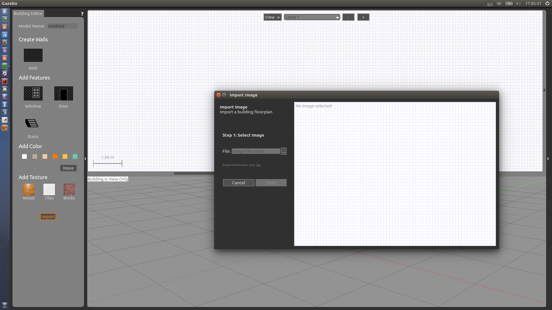
Import a floor plan
You may create a scene from scratch, or use an existing image as a template to trace over. This image can be, for example, a 2D laser scan of a building.
Click here to get an example floor plan, then proceed as follows:
Click on the
Importbutton. TheImport Imagedialog will come up.Step 1: Choose the image you previously saved on your computer and click
Next.
Step 2: To make sure the walls you trace over the image come up in the correct scale, you must set the image's resolution in pixels per meter (
px/m). If we knew the resolution, we could directly type it in the dialog and clickOk. In this example we don't know the resolution, but we know the real-world distance between two points in the image (for example, the top wall of 7.5 m), so we can use that to calculate the resolution:a. Click/release on one end of the wall. As you move the mouse, an orange line will appear as shown below.
b. Click/release at the end of the wall to complete the line.
c. Now type the distance in meters in the dialog (7.5 m in this case). The resolution will be automatically calculated for you based on the line you drew.
d. You can then click
Ok.
The image will appear on the 2D View properly scaled.
Tip: Once you've added more levels, you can import a floor plan for each by repeating the same process.
Add features
Add walls
Trace all walls on the floor plan as follows. Keep in mind that we will attach windows and doors to the walls later, so here you can draw the walls over them. Don't worry too much if the walls are not perfect, we will edit them later.
On the Palette, click on
Wall.On the 2D View, click/release anywhere to start the wall. As you move the mouse, the wall's length is displayed.
Click again to end the current wall and start an adjacent wall.
Double-click to finish a wall without starting a new one.
Tip: You can right-click or press
Escto cancel drawing the current wall segment.Tip: By default, walls snap to 15° and 0.25 m increments and also to the end points of existing walls. To override this, hold
Shiftwhile drawing.
Add windows and doors
Note: Currently, windows and doors are simple holes in the wall.
Let's insert windows and doors at the locations shown on the floor plan.
On the Palette, click on
WindoworDoor.As you move the mouse in the 2D view, the feature to be inserted moves with it, as does its counterpart in the 3D View.
Tip: Windows and doors automatically snap to walls as you hover over them. The distances to the ends of the wall are displayed as you move.
Click on the desired position to place the feature.

Tip: It might be difficult to see where the features are on your floor plan after the walls have been drawn on top of it. To make it easier, at the top of the 2D View, you can choose to view or hide the floor plan or features for the current level. You can also use hotkeys to toggle visibility,
Ffor floor plan andGfor features.
Add stairs
There are no staircases on this floor plan, but we will insert one anyways.
On the Palette, click on
Stairs.As you move the mouse in the 2D view, the staircase to be inserted moves with it, as does its counterpart in the 3D View.
Choose a position for your staircase and click to place it.

Add levels
We're pretty much done with Level 1. Let's add another level to our building so our staircase ends up somewhere.
At the top of the 2D View, click on + to add a level. Alternatively, right-click the 2D View and choose Add a level.
When a new level is added, a floor is automatically inserted. If there are stairs on the level below, a hole above the stairs will be cut out from the floor when the building is saved.
Note: Currently, all floors are rectangular.
Tip: Before adding a level, make sure you have walls on the current level to build on top of.
Tip: Currently, all the walls from the level below are copied to the new level, with default materials. No other features are copied. You can manually delete the walls you don't want.

Edit your building
Note: Be careful when editing your building; the editor currently has no option to undo your actions.
Tip: All measurements are in meters.
Change levels
Since we added a level, we were brought to the new level in the 2D view. You can go back to Level 1 by choosing it from the drop-down list at the top of the 2D View.
Tip: The level currently selected in the 2D View will appear as semi-transparent in the 3D View and all levels below it will appear opaque. Levels above will be hidden - but keep in mind they are still part of your building!
We can also edit some level configurations if we want.
- Double-click the 2D View to open an inspector with level configuration options. Alternatively, right-click and choose
Open Level Inspector.
You may have added levels that you don't want, or perhaps made a mess in the current level and would like to start it over.
To delete the current level, either press the
-button at the top of the 2D View, or right-click and chooseDelete Level.
Edit walls
We drew a lot of walls earlier, but maybe they didn't turn out exactly the way we wanted.
In the 2D View, click on the wall to be edited.
a. Translate the wall by dragging it to a new position.
b. Resize or rotate the wall by dragging one of its end points.
Tip: By default, walls snap to 15° and 0.25 m increments. To override this, hold
Shiftwhile drawing.Double-click a wall in the 2D View to open an inspector with configuration options. Alternatively, right-click and choose
Open Wall Inspector. Edit some fields and pressApplyto preview the changes.To delete a wall, either press the
Deletekey while it is selected, or right-click the wall in the 2D View and chooseDelete.Tip: Editing a wall takes attached walls into account.
Tip: Deleting a wall deletes all doors and windows attached to it.

Edit windows and doors
Now let's play around with windows and doors. As we did for the walls, we can manipulate windows and doors more precisely in a few different ways.
In the 2D View, click on the feature to be edited.
a. Translate the feature by dragging it to a new position. Remember that windows and doors automatically snap to walls and it doesn't make much sense to have them detached from any walls, as they represent holes in a wall.
b. Rotate the feature by dragging its rotation handle. Currently, as long as they are attached to a wall, their orientation doesn't make a difference.
c. Resize the feature's width by dragging one of the end points.
Double-click a feature in the 2D View to open an inspector with configuration options. Alternatively, right-click and choose
Open Window/Door Inspector.To delete a feature, either press the
Deletekey while it is selected, or right-click it in the 2D View and chooseDelete.
Edit stairs
Finally, let's edit the staircase we inserted earlier. Since it is not on the floor plan, we can get creative and resize it as we want.
In the 2D View, click on the staircase to select it.
a. Translate the staircase by dragging it to a new position.
b. Rotate the staircase in multiples of 90° by dragging its rotation handle.
c. Resize the staircase by dragging one of the end nodes.
Double-click the staircase in the 2D View to open an inspector with configuration options. Alternatively, right-click and choose
Open Stairs Inspector.To delete the staircase, either press the
Deletekey while it is selected, or right-click and chooseDelete.
Tip: In the 2D View, staircases are visible on both the start and end levels.

Add colors and textures
Now that everything is properly placed and sized, you can assign colors and textures to walls, floors and staircases. Remember that windows and doors are only holes on the wall and therefore cannot have materials.
Tip: The default color is white and the default texture is none.
There are two ways to add colors and textures to your building:
From Inspectors
You can add color and texture to walls, stairs and floors from the Wall Inspector, Stairs Inspector and Level Inspector respectively. Simply open the inspector, select your materials and press Apply.

From the Palette
Colors and textures can be chosen from the Palette and assigned to items on your building by clicking on them in the 3D View.
Click on a color or texture in the Palette.
As you move your mouse in the 3D View, hovered features will be highlighted displaying a preview of the selected material.
Clicking on the highlighted feature assigns the selected material to it. You can click on as many features as you'd like.
When you're done with the selected material, either right-click the 3D view, or click outside any features to leave the material mode.

New in Gazebo 5.1: To choose a custom color, click on
Moreon the Palette. A dialog opens where you can specify custom colors.
Tip: Each feature can have only one color and one texture. The same material is assigned to all faces of the feature.
Note: Currently, it is not possible to assign custom textures on the Building Editor.
Saving your building
Saving will create a directory, SDF and config files for your building.
Before saving, give your building a name on the Palette.

On the top menu, choose File, then Save As (or hit Ctrl+S). A dialog will come up where you can choose the location for your model.
Tip: Under
Advanced Optionsyou can set some meta-data for your building.

Exit
Note: Once you exit the Building Editor, your building will no longer be editable.
When you're done creating your building and you've saved it, go to File and then Exit Building Editor.
Your building will show up in the main window. In the future, you can find the building in your Insert tab.


 9449
9449

 被折叠的 条评论
为什么被折叠?
被折叠的 条评论
为什么被折叠?
 到【灌水乐园】发言


