


问题:
1 广角/超广角与鱼眼摄像机,角度界限
2 畸变模型中radtan畸变模型与鱼眼畸变模型在小于150范围是否都时能适用. (同数据,拟合模型不同,,参数结果不同,不欠拟合和过拟合就可)
3 FOV畸变模型与鱼眼畸变模型中体视投影的关系.
鱼眼相机模型 (fisheye camera model)
模型介绍
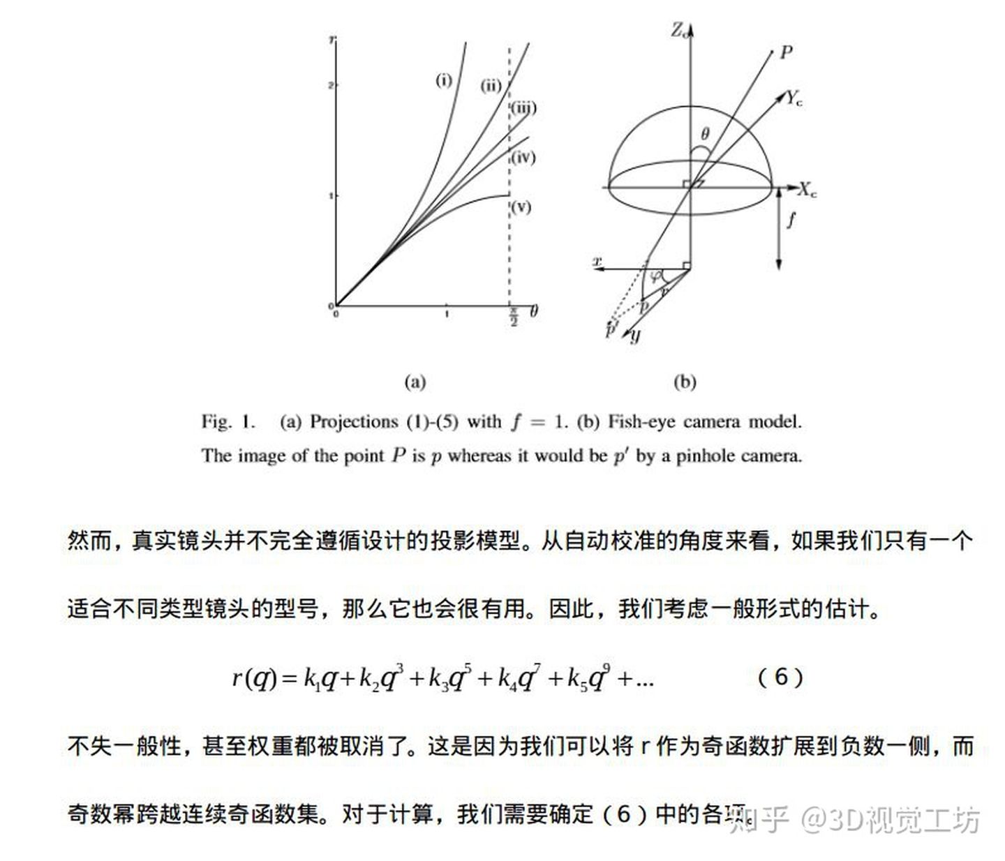
等距投影
等立体角投影
正交投影
体视投影
线性投影
Kannala-Brandt 模型
去畸变过程
投影过程
反投影过程
雅可比计算
之前总结了一下针孔相机的模型,然后得到了比较积极的回复(其实是我到处求人关注的,虽然截至到目前才三个人),所以就再接再励,乘胜追击(也没得办法,夸下的海口,跪着也要做完),继续总结其他相机模型。
模型介绍
鱼眼相机相较于针孔相机来说,视野更广,但畸变也更加严重,因此普通的针孔模型已不适用。鱼眼镜头的基本构造如图所示,经过多个镜头的折射,最终到达成像单元上。文章中所有图片均来自于网络,非本人所绘。
一般情况下,可以通过控制光线的路径来设计各种各样的镜头类型,根据投影方式的不同,可以将这些镜头分为等距投影、等立体角投影、正交投影、体视投影以及线性投影。


等距投影
r = f θ r=f*θ
等立体角投影
r = 2 f s i n ( θ /2 ) r=2*f*sin(θ/2)
正交投影
r = f s i n ( θ ) r=f*sin(θ)
体视投影
r = 2 f t a n ( θ/ 2 ) r=2*f*tan(θ/2)
线性投影
r = f t a n ( θ ) r=f*tan(θ)
Kannala-Brandt 模型
同针孔模型一样,鱼眼模型也有畸变,那么怎么来用数学鱼眼描述这种畸变呢?观察各种投影方式,发现他们都是一个关于入射角 θ 的奇函数,因此鱼眼镜头的畸变也是对 θ的畸变,KB模型用只包含奇次项的多项式来描述畸变过程,其具体形式如下所示

θ d = θ + k 1 θ 3 + k 2 θ 5 + k 3 θ 7 + k 4 θ 9 θd=θ+k1θ3+k2θ5+k3θ7+k4θ9
opencv中使用的鱼眼相机畸变模型就是这个模型,该模型适用于大多数鱼眼相机。另外,也可以用这种模型来对普通的针孔相机模型进行标定,仔细观察,上述的线性投影实际就是普通的针孔投影模型。最后鱼眼相机的投影模型可以表示为
r = f θ d r=fθd (kalibr工具, Equidistant模型,)
其中 r 表示图像中像素点到主点的距离。
去畸变过程
对于鱼眼相机的去畸变过程可以采用解析的方式,因为从上述畸变公式中可以看到,畸变模型是一个多项式,理论上是存在解析解的。但本人使用的方法和针孔模型中类似,通过优化的方法进行去即便,代码如下
      template<typename DERIVED_P>
      void undistort(const Eigen::MatrixBase <DERIVED_P> &p_d,const Eigen::MatrixBase <DERIVED_P> &p_ud) const
      {
          EIGEN_STATIC_ASSERT_VECTOR_SPECIFIC_SIZE_OR_DYNAMIC(Eigen::MatrixBase<DERIVED_P>, 2)
          Eigen::MatrixBase<DERIVED_P> &y_ud = const_cast<Eigen::MatrixBase<DERIVED_P> &>(p_ud);
          Eigen::MatrixBase<DERIVED_P> &y_d = const_cast<Eigen::MatrixBase<DERIVED_P> &>(p_d);
          y_ud.derived().resize(2);
          y_d.derived().resize(2);

          struct MLFunctor{
              MLFunctor( const Eigen::Vector2d &imagePoint, double k1, double k2, double k3, double k4 )
                      : imagePoint_(imagePoint), _k1(k1), _k2(k2), _k3(k3), _k4(k4)
              {
              }

              int operator( )( const Eigen::VectorXd &x, Eigen::VectorXd &fvec ) const{

                  double theta = x[0];
                  double phi = x[1];
                  double theta2 = theta * theta;
				  double theta4 = theta2 * theta2;
				  double theta6 = theta4 * theta2;
				  double theta8 = theta4 * theta4;
                  double thetad = theta * ( 1 + _k1 * theta2 + _k2 * theta4 + _k3 * theta6 + _k4 * theta8);
                  fvec[0] = thetad;
                  fvec[1] = phi;
                  fvec = fvec - imagePoint_;
                  return 0;
              }

              int df( const Eigen::VectorXd &x, Eigen::MatrixXd &fjac ) const
              {
                  double theta = x[0];
                  double theta2 = theta * theta;
				  double theta4 = theta2 * theta2;
				  double theta6 = theta4 * theta2;
				  double theta8 = theta4 * theta4;

                  fjac(0, 0) = 9 * _k4 * theta8 + 7 * _k3 * theta6 + 5 * _k2 * theta4 + 3 * _k1 * theta2 + 1;
                  fjac(0, 1) = 0;
                  fjac(1, 0) = 0;
                  fjac(1, 1) = 1;

                  return 0;
              }

              int values() const { return 2; }
              int inputs() const { return 2; }

              Eigen::Vector2d imagePoint_;

              double _k1;
              double _k2;
              double _k3;
              double _k4;
          };

          Eigen::Vector2d target = y_d;
          MLFunctor func( target, m_k1, m_k2, m_k3, m_k4 );
          Eigen::LevenbergMarquardt< MLFunctor > lm(func);
          double theta = y_d[0];
          double phi = y_d[1];

          Eigen::VectorXd res = Eigen::Vector2d(theta, phi);
          lm.minimize(res);
          y_ud = res;
      }
投影过程

反投影过程

雅可比计算
多数情况下,都用BA算法来计算相机的内外参,这就需要知道雅可比矩阵,即投影误差对各待优化变量的偏导数组成的矩阵。所谓的投影误差,实际检测到点与投影到图像上的点之间的误差

e r r = p m − p err=pm−p
其中 pm表示检测到的角点。为了避免手撕公式,我使用了matlab直接来推导出结果,并且在推导公式时,没有考虑畸变项,因为公式太长了,懒得敲。
代码:
syms fx fy x y z cx cy k1 k2 k3 k4

R = sqrt(x^2 + y^2 + z^2);
xc = x / R;
yc = y / R;
zc = z / R;
theta = acos(z);
%thetad = theta + k1 * theta^3 + k2 * theta^5 + k3 * theta^7 + k4 * theta^9;
thetad = theta;
r = sqrt(xc^2 + yc^2);
u = fx * (thetad * xc) / r + cx;
v = fy * (thetad * yc) / r + cy;

alphaE_alphaK = - [diff(u, fx), diff(u, fy), diff(u, cx), diff(u, cy);
                   diff(v, fx), diff(v, fy), diff(v, cx), diff(v, cy)]

alphaE_alphaP = -[diff(u, x), diff(u, y), diff(u, z);
                diff(v, x), diff(v, y), diff(v, z)]
alphaP_alphaR = [1, 0, 0, 0, z, -y;
                 0, 1, 0, -z, 0, x;
                 0, 0, 1, y, -x, 0]

alphaE_alphaP * alphaP_alphaR
假设相机坐标系下归一化到球面的3D点坐标坐标为Ps=(xs,ys,zs)
1. 误差项关于内参的偏导数

其中![]() 。
。
2.误差项关于相机坐标系下点Ps的偏导
其中![]() 。
。
3.误差项在李代数上的扰动模型
根据链式法则可得

其中, ∂ P c/∂ δ ξ的推导后续会有专门篇幅进行总结,在这个先用起来再说。

其中![]() 。
。
————————————————
原文链接:https://blog.csdn.net/weixin_43304707/article/details/113261307
鱼眼相机标定以及OpenCV实现
在另一篇文章中我已经写过有关普通相机模型及其OpenCV标定实现,这篇文章将主要关注鱼眼相机模型及其OpenCV标定实现。
先看一张鱼眼相机拍摄出来的结果:

从图中可以看出很明显的畸变。对鱼眼相机标定,有时候也可以用普通相机的标定方法对其进行标定,但是却不能保证去畸变后的效果是最好的。因此对于Gopro等鱼眼镜头拍摄出来的图像去畸变,最好的方法就是采用鱼眼相机标定方法进行标定。
鱼眼相机模型
鱼眼相机的内参模型依然可以表示为:

这与普通镜头的成像模型没有区别。两者之间的区别主要体现在畸变系数,鱼眼相机的畸变系数为{ k1,k2,k3,k4},畸变系数不同,就导致鱼眼相机的投影关系也发生了变化,主要变化发生在考虑畸变情况下的投影关系转化:
设(X,Y,Z)为空间中一个三维点,它在成像平面内的成像坐标为(u,v),在考虑畸变的情况下,
OpenCV实现鱼眼相机标定
利用opencv实现鱼眼相机的标定和普通相机标定的标定流程基本一致,具体流程如下:
1. 检测角点
cv::findChessboardCorners(InputArray image, Size patternSize, OutputArray corners, int
flags=CALIB_CB_ADAPTIVE_THRESH+CALIB_CB_NORMALIZE_IMAGE}
获得棋盘标定板的角点位置,使用
cornerSubPix(InputArray image, InputOutputArray corners, Size winSize, Size zeroZone,
TermCriteria criteria)获取角点更精细的检测结果
2. 初始化标定板上角点的三维坐标
3. 开始标定
double fisheye::calibrate(InputArrayOfArrays objectPoints, InputArrayOfArrays imagePoints,
const Size& image_size, InputOutputArray K, InputOutputArray D,
OutputArrayOfArrays rvecs, OutputArrayOfArrays tvecs, int flags=0,
TermCriteria criteria=TermCriteria(TermCriteria::COUNT + TermCriteria::
EPS, 100, DBL_EPSILON))
注意:K,D 分别表示内参矩阵和畸变系数向量,在定义时要定义为double型,这里推荐使用Matx33d和Vec4d数据类型,更为方便简单。objectPoints,imagePoints可以是float型,也可以是double型,但是再stereorectify中需要时double型。flags的可选项有很多,其中需要注意的是必须要指定CALIB_FIX_SKEW,代表求解时假设内参中fx=fy
.
4.评定误差(可选项)
以上就是鱼眼相机标定的基本流程,部分代码片段如下:
    for (int i = 0; i != image_count; i++)
    {
        cout << "Frame #" << i + 1 << "..." << endl;
        string image_Name;
        stringstream stream;
        stream << (i + startNum);
        stream >> image_Name;
        image_Name = path_ChessboardImage + image_Name + ".jpg";
        cv::Mat image = imread(image_Name);
        Mat image_gray;
        cvtColor(image, image_gray, CV_RGB2GRAY);
        vector<Point2f> corners;
        bool patternFound = findChessboardCorners(image_gray, board_size, corners,
            CALIB_CB_ADAPTIVE_THRESH + CALIB_CB_NORMALIZE_IMAGE + CALIB_CB_FAST_CHECK);
        if (!patternFound || fullcornersNum != corners.size())
        {
            cout << "can not find chessboard corners!\n";
            continue;
        }
        else
        {
            cornerSubPix(image_gray, corners, Size(11, 11), Size(-1, -1), TermCriteria(CV_TERMCRIT_EPS + CV_TERMCRIT_ITER, 30, 0.1));
            count = count + corners.size();
            corners_Seq.push_back(corners);
            successImageNum = successImageNum + 1;
            image_Seq.push_back(image);
        }
    }
    /************************************************************************
    摄像机定标
    *************************************************************************/
    vector<vector<Point3f>>  object_Points;        /****  保存定标板上角点的三维坐标   ****/

    Mat image_points = Mat(1, count, CV_32FC2, Scalar::all(0));  /*****   保存提取的所有角点   *****/
    vector<int>  point_counts;
    /* 初始化定标板上角点的三维坐标 */
    for (int t = 0; t<successImageNum; t++)
    {
        vector<Point3f> tempPointSet;
        for (int i = 0; i<board_size.height; i++)
        {
            for (int j = 0; j<board_size.width; j++)
            {
                /* 假设定标板放在世界坐标系中z=0的平面上 */
                Point3f tempPoint;
                tempPoint.x = i*square_size.width;
                tempPoint.y = j*square_size.height;
                tempPoint.z = 0;
                tempPointSet.push_back(tempPoint);
            }
        }
        object_Points.push_back(tempPointSet);
    }
    for (int i = 0; i< successImageNum; i++)
    {
        point_counts.push_back(board_size.width*board_size.height);
    }
    /* 开始定标 */
    Size image_size = image_Seq[0].size();
    cv::Matx33d intrinsic_matrix;    /*****    摄像机内参数矩阵    ****/
    cv::Vec4d distortion_coeffs;     /* 摄像机的4个畸变系数:k1,k2,k3,k4*/
    std::vector<cv::Vec3d> rotation_vectors;                           /* 每幅图像的旋转向量 */
    std::vector<cv::Vec3d> translation_vectors;                        /* 每幅图像的平移向量 */
    int flags = 0;
    flags |= cv::fisheye::CALIB_RECOMPUTE_EXTRINSIC;
    flags |= cv::fisheye::CALIB_CHECK_COND;
    flags |= cv::fisheye::CALIB_FIX_SKEW;
    fisheye::calibrate(object_Points, corners_Seq, image_size, intrinsic_matrix, distortion_coeffs, rotation_vectors, translation_vectors, flags, cv::TermCriteria(3, 20, 1e-6));
标定结果:
————————————————
原文链接:https://blog.csdn.net/u010784534/article/details/50474371
│ │ ├── samples
│ │ │ ├── multi_cameras_calibration.cpp
│ │ │ ├── omni_calibration.cpp
│ │ │ ├── omni_stereo_calibration.cpp
│ │ │ ├── random_pattern_calibration.cpp
│ │ │ └── random_pattern_generator.cpp
│ │ ├── src
│ │ │ ├── ccalib.cpp
│ │ │ ├── multicalib.cpp
│ │ │ ├── omnidir.cpp
│ │ │ ├── precomp.hpp
│ │ │ └── randpattern.cpp
│ │ └── tutorials

文章目录
Overview
Camera models
Pinhole
omnidirectional
Distortion models
Equidistant (EQUI)
Radtan
FOV
Projection model
Full projection model
MEI Camera
Pinhole Camera
atan Camera
Davide Scaramuzza Camera
Examples
C++ Code
Reference
Overview
鱼眼镜头的成像原理分类123:
Dioptric cameras,通过透镜来实现,主要是折射
Catadioptric cameras,使用一个标准相机加一个面镜(Shaped mirror)
polydioptric camera,通过多个相机重叠视野
目前的视觉系统都是 central 的,入射光线会相交于同一点,点称为 single effective viewpoint。
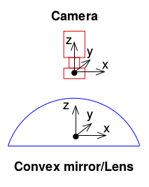
全向相机 (omnidirectional camera )建模要考虑 mirror 反射或者鱼眼镜头折射。如下图所示。
Camera models
参考自45
Pinhole
参数: [ f x f y c x c y ]

// cam2world
if(!distortion_)
  {
    xyz[0] = (u - cx_)/fx_;
    xyz[1] = (v - cy_)/fy_;
    xyz[2] = 1.0;
  }

// world2cam
  if(!distortion_)
  {
    px[0] = fx_*uv[0] + cx_;
    px[1] = fy_*uv[1] + cy_;
  }
omnidirectional
参数: [ ξ f x f y c x c y ] X=[X,Y,Z]到球面上

变换坐标系,并变换到归一化平面

然后可以加入畸变,这里先不考虑。
然后使用相机内参,和公式(1)一样:
其中公式(3)中的逆变换,即从图像系得到球面公式(2)公式为
相应的得到归一化平面坐标为(比较奇怪的一个坐标):
// cam2world
// 像素坐标变换到球面
mx_u = m_inv_K11 * p(0) + m_inv_K13;
my_u = m_inv_K22 * p(1) + m_inv_K23;

double xi = mParameters.xi();
if (xi == 1.0)
{
    lambda = 2.0 / (mx_u * mx_u + my_u * my_u + 1.0);
    P << lambda * mx_u, lambda * my_u, lambda - 1.0;
}
else
{
    lambda = (xi + sqrt(1.0 + (1.0 - xi * xi) * (mx_u * mx_u + my_u * my_u))) / (1.0 + mx_u * mx_u + my_u * my_u);
    P << lambda * mx_u, lambda * my_u, lambda - xi;
}


// 或者变换到归一化平面
if (xi == 1.0)
{
    P << mx_u, my_u, (1.0 - mx_u * mx_u - my_u * my_u) / 2.0;
}
else
{
    // Reuse variable
    rho2_d = mx_u * mx_u + my_u * my_u;
    P << mx_u, my_u, 1.0 - xi * (rho2_d + 1.0) / (xi + sqrt(1.0 + (1.0 - xi * xi) * rho2_d));
}

// 正向比较简单,按照公式来就行了,代码忽略

Distortion models
Equidistant (EQUI) 等距投影 , r=f*θ

float ix = (x - ocx) / ofx;
float iy = (y - ocy) / ofy;
float r = sqrt(ix * ix + iy * iy);
float theta = atan(r);
float theta2 = theta * theta;
float theta4 = theta2 * theta2;
float theta6 = theta4 * theta2;
float theta8 = theta4 * theta4;
float thetad = theta * (1 + k1 * theta2 + k2 * theta4 + k3 * theta6 + k4 * theta8);
float scaling = (r > 1e-8) ? thetad / r : 1.0;
float ox = fx*ix*scaling + cx;
float oy = fy*iy*scaling + cy;
Radtan (radial径向 + Tangent切向)

其中x,y是不带畸变的坐标, xdistorted,ydistorted是有畸变图像的坐标。
// cam2world(distorted2undistorted)
// 先经过内参变换,再进行畸变矫正
{
  cv::Point2f uv(u,v), px;
  const cv::Mat src_pt(1, 1, CV_32FC2, &uv.x);
  cv::Mat dst_pt(1, 1, CV_32FC2, &px.x);
  cv::undistortPoints(src_pt, dst_pt, cvK_, cvD_);
  xyz[0] = px.x;
  xyz[1] = px.y;
  xyz[2] = 1.0;
}
// 先经过镜头发生畸变,再成像过程,乘以内参
// world2cam(undistorted2distorted)
{
  double x, y, r2, r4, r6, a1, a2, a3, cdist, xd, yd;
  x = uv[0];
  y = uv[1];
  r2 = x*x + y*y;
  r4 = r2*r2;
  r6 = r4*r2;
  a1 = 2*x*y;
  a2 = r2 + 2*x*x;
  a3 = r2 + 2*y*y;
  cdist = 1 + d_[0]*r2 + d_[1]*r4 + d_[4]*r6;
  xd = x*cdist + d_[2]*a1 + d_[3]*a2;
  yd = y*cdist + d_[2]*a3 + d_[3]*a1;
  px[0] = xd*fx_ + cx_;
  px[1] = yd*fy_ + cy_;
}
FOV

体视投影 r=2*f*tan(θ/2)
// cam2world(distorted2undistorted)
Vector2d dist_cam( (x - cx_) * fx_inv_, (y - cy_) * fy_inv_ );
double dist_r = dist_cam.norm();
double r = invrtrans(dist_r);
double d_factor;
if(dist_r > 0.01)
  d_factor =  r / dist_r;
else
  d_factor = 1.0;
return unproject2d(d_factor * dist_cam).normalized();


// world2cam(undistorted2distorted)
double r = uv.norm();
double factor = rtrans_factor(r);
Vector2d dist_cam = factor * uv;
return Vector2d(cx_ + fx_ * dist_cam[0],
                  cy_ + fy_ * dist_cam[1]);

// 函数
//! Radial distortion transformation factor: returns ration of distorted / undistorted radius.
inline double rtrans_factor(double r) const
{
  if(r < 0.001 || s_ == 0.0)
    return 1.0;
  else
    return (s_inv_* atan(r * tans_) / r);
};

//! Inverse radial distortion: returns un-distorted radius from distorted.
inline double invrtrans(double r) const
{
  if(s_ == 0.0)
    return r;
  return (tan(r * s_) * tans_inv_);
};
Projection model
Full projection model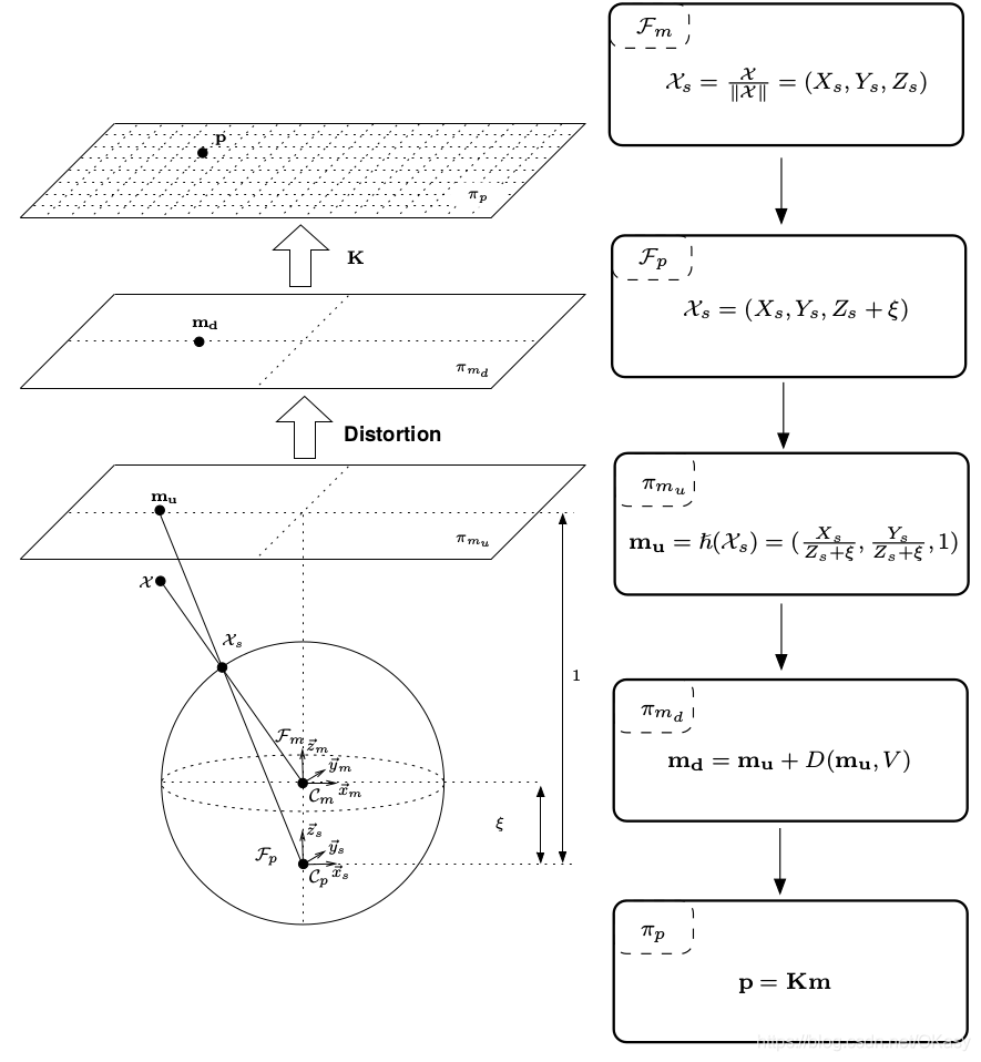
第一步是将mirror系下的世界坐标点投影到归一化球面(unit sphere)

将投影点的坐标变换到一个新坐标系下表示,新坐标系的原点位于 C p = ( 0 , 0 , ξ ) \mathcal{C}_{p}=(0,0, \xi) Cp=(0,0,ξ)

将其投影到归一化平面

增加畸变影响

乘上相机模型内参矩阵 K \bf K K,其中 γ \gamma γ表示焦距, ( u 0 , v 0 ) (u_0,v_0) (u0,v0)表示光心, s s s表示坐标系倾斜系数, r r r表示纵横比

下图是相机焦距与面镜类型的参数对比。

MEI Camera
Omni + Radtan(6)
Pinhole Camera
Pinhole + Radtan
atan Camera
Pinhole + FOV
Davide Scaramuzza Camera
参数: [ P o l y [ N ] , C , D , E , x c , y c

这个是ETHZ的工作7,畸变和相机内参放在一起了,为了克服针对鱼眼相机参数模型的知识缺乏,使用一个多项式来代替。
直接上代码吧:
// ************************** world2cam **************************
Vector2d uv;

// transform world-coordinates to Davide's camera frame
Vector3d worldCoordinates_bis;
worldCoordinates_bis[0] = xyz_c[1];
worldCoordinates_bis[1] = xyz_c[0];
worldCoordinates_bis[2] = -xyz_c[2];

double norm = sqrt( pow( worldCoordinates_bis[0], 2 ) + pow( worldCoordinates_bis[1], 2 ) );
double theta = atan( worldCoordinates_bis[2]/norm );

// Important: we exchange x and y since Pirmin's stuff is working with x along the columns and y along the rows,
// Davide's framework is doing exactly the opposite
double rho;
double t_i;
double x;
double y;

if(norm != 0)
{
  rho = ocamModel.invpol[0];

  t_i = 1;
  // 多项式畸变
  for( int i = 1; i < ocamModel.length_invpol; i++ )
  {
    t_i *= theta;
    rho += t_i * ocamModel.invpol[i];
  }

  x = worldCoordinates_bis[0] * rho/norm;
  y = worldCoordinates_bis[1] * rho/norm;

  //? we exchange 0 and 1 in order to have pinhole model again
  uv[1] = x * ocamModel.c + y * ocamModel.d + ocamModel.xc;
  uv[0] = x * ocamModel.e + y + ocamModel.yc;
}
else
{
  // we exchange 0 and 1 in order to have pinhole model again
  uv[1] = ocamModel.xc;
  uv[0] = ocamModel.yc;
}


//******************** cam2world ******************
double invdet  = 1 / ( ocamModel.c - ocamModel.d * ocamModel.e );

xyz[0] = invdet * ( ( v - ocamModel.xc ) - ocamModel.d * ( u - ocamModel.yc ) );
xyz[1] = invdet * ( -ocamModel.e * ( v - ocamModel.xc ) + ocamModel.c * ( u - ocamModel.yc ) );

double r = sqrt(  pow( xyz[0], 2 ) + pow( xyz[1], 2 ) ); //distance [pixels] of  the point from the image center
xyz[2] = ocamModel.pol[0];
double r_i = 1;

for( int i = 1; i < ocamModel.length_pol; i++ )
{
  r_i *= r;
  xyz[2] += r_i * ocamModel.pol[i];
}

xyz.normalize();

// change back to pinhole model:
double temp = xyz[0];
xyz[0] = xyz[1];
xyz[1] = temp;
xyz[2] = -xyz[2];
Examples
据大佬说,根据经验,小于90度使用Pinhole,大于90度使用MEI模型。
要注意畸变矫正之后的相机内参会变化。
DSO:Pinhole + Equi / Radtan / FOV
VINS:Pinhole / Omni + Radtan
SVO:Pinhole / atan / Scaramuzza
OpenCV:cv: pinhole + Radtan , cv::fisheye: pinhole + Equi , cv::omnidir: Omni + Radtan
C++ Code
https://github.com/alalagong/CameraModel
Reference
https://blog.csdn.net/zhangjunhit/article/details/89137958 ↩︎
https://blog.csdn.net/u011178262/article/details/86656153#OpenCV_fisheye_camera_model_61
https://github.com/ethz-asl/kalibr/wiki/supported-models
https://github.com/hengli/camodocal
https://github.com/uzh-rpg/rpg_vikit
Mei C, Rives P. Single view point omnidirectional camera calibration from planar grids[C]//Proceedings 2007 IEEE International Conference on Robotics and Automation. IEEE, 2007: 3945-3950.
Kneip L, Scaramuzza D, Siegwart R. A novel parametrization of the perspective-three-point problem for a direct computation of absolute camera position and orientation[C]//CVPR 2011. IEEE, 2011: 2969-2976.
————————————————
原文链接:https://blog.csdn.net/okasy/article/details/90665534


 5322
5322

 被折叠的 条评论
为什么被折叠?
被折叠的 条评论
为什么被折叠?
 到【灌水乐园】发言


