


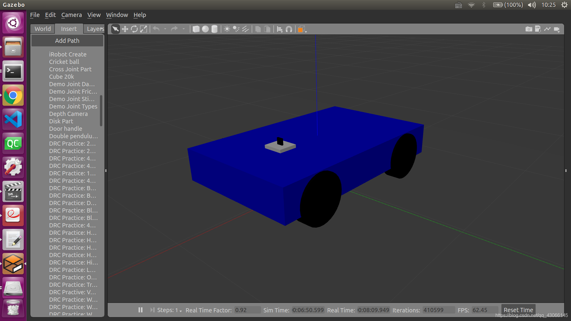
在搭建完机器人小车的模型之后,需要向其添加传感器,以便提取传感器的数据,进行后续的工作。
一、相机
1.添加camera_gazebo.xacro文件
同添加机器人模型一样,添加一个相机也需要进行定义一个相机的结构,参数,功能的“类”,也就是camera.xacro文件,在总的调用文件“shcRobot2_xacro_camera_gazebo.xacro”中调用即可。具体代码来源于参考文献1
<?xml version="1.0"?>
<robot xmlns:xacro="http://www.ros.org/wiki/xacro" name="camera">

    <xacro:macro name="usb_camera" params="prefix:=camera">
        <!-- Create laser reference frame -->
        <link name="${prefix}_link">
            <inertial>
                <mass value="0.1" />
                <origin xyz="0 0 0" />
                <inertia ixx="0.01" ixy="0.0" ixz="0.0"
                         iyy="0.01" iyz="0.0"
                         izz="0.01" />
            </inertial>

            <visual>
                <origin xyz=" 0 0 0 " rpy="0 0 0" />
                <geometry>
                    <box size="0.01 0.04 0.04" />
                </geometry>
                <material name="black"/>
            </visual>

            <collision>
                <origin xyz="0.0 0.0 0.0" rpy="0 0 0" />
                <geometry>
                    <box size="0.01 0.04 0.04" />
                </geometry>
            </collision>
        </link>
        <gazebo reference="${prefix}_link">
            <material>Gazebo/Black</material>
        </gazebo>

        <gazebo reference="${prefix}_link">
            <sensor type="camera" name="camera_node">
                <update_rate>30.0</update_rate>
                <camera name="head">
                    <horizontal_fov>1.3962634</horizontal_fov>
                    <image>
                        <width>1280</width>
                        <height>720</height>
                        <format>R8G8B8</format>
                    </image>
                    <clip>
                        <near>0.02</near>
                        <far>300</far>
                    </clip>
                    <noise>
                        <type>gaussian</type>
                        <mean>0.0</mean>
                        <stddev>0.007</stddev>
                    </noise>
                </camera>
                <plugin name="gazebo_camera" filename="libgazebo_ros_camera.so">
                    <alwaysOn>true</alwaysOn>
                    <updateRate>0.0</updateRate>
                    <cameraName>/camera</cameraName>
                    <imageTopicName>image_raw</imageTopicName>
                    <cameraInfoTopicName>camera_info</cameraInfoTopicName>
                    <frameName>camera_link</frameName>
                    <hackBaseline>0.07</hackBaseline>
                    <distortionK1>0.0</distortionK1>
                    <distortionK2>0.0</distortionK2>
                    <distortionK3>0.0</distortionK3>
                    <distortionT1>0.0</distortionT1>
                    <distortionT2>0.0</distortionT2>
                </plugin>
            </sensor>
        </gazebo>

    </xacro:macro>
</robot>
2.调用camera_gazebo.xacro文件生成总模型
在下面的总调用文件“shcRobot2_xacro_camera_gazebo.xacro”中,除了要引用camera.xacro文件,还要记得定义camera和base_link的连接节点的位置和属性。
<?xml version="1.0"?>
<robot name="arm" xmlns:xacro="http://www.ros.org/wiki/xacro">
    <xacro:include filename="$(find shcrobot_description)/urdf/xacro/shcRobot2_base_gazebo.xacro"/>
    <xacro:include filename="$(find shcrobot_description)/urdf/xacro/camera_gazebo.xacro"/>

    <xacro:property name="camera_offset_x" value="0.3" />
    <xacro:property name="camera_offset_y" value="0" />
    <xacro:property name="camera_offset_z" value="0.14" />

    <robot_base/>

    <!-- Camera -->
    <joint name="camera_joint" type="fixed">
        <origin xyz="${camera_offset_x} ${camera_offset_y} ${camera_offset_z}" rpy="0 0 0" />
        <parent link="base_link"/>
        <child link="camera_link"/>
    </joint>
    <xacro:usb_camera prefix="camera"/>
</robot>
3.修改相应launch文件,启动仿真
<launch>
	    <!-- 设置launch文件的参数 -->
    <arg name="paused" default="false"/>
    <arg name="use_sim_time" default="true"/>
    <arg name="gui" default="true"/>
    <arg name="headless" default="false"/>
    <arg name="debug" default="false"/>

	<!--运行gazebo仿真环境-->
	<include file="$(find gazebo_ros)/launch/empty_world.launch">
        	<arg name="debug" value="$(arg debug)" />
        	<arg name="gui" value="$(arg gui)" />
        	<arg name="paused" value="$(arg paused)"/>
        	<arg name="use_sim_time" value="$(arg use_sim_time)"/>
        	<arg name="headless" value="$(arg headless)"/>
    	</include>


	<!-- 加载机器人模型描述参数 -->
	<param name="robot_description" command="$(find xacro)/xacro --inorder '$(find shcrobot_description)/urdf/xacro/shcRobot2_xacro_camera_gazebo.xacro'"/>
	<!--运行joint_state_publisher节点,发布机器人关节状态-->
	<node name = "robot_state_publisher" pkg = "robot_state_publisher" type = "state_publisher">
		<param name="publish_frequency" type="double" value="20.0" />
	</node>
	    <!-- 在gazebo中加载机器人模型-->
    <node name="urdf_spawner" pkg="gazebo_ros" type="spawn_model" respawn="false" output="screen"
          args="-urdf -model shcrobot -param robot_description"/>
</launch>
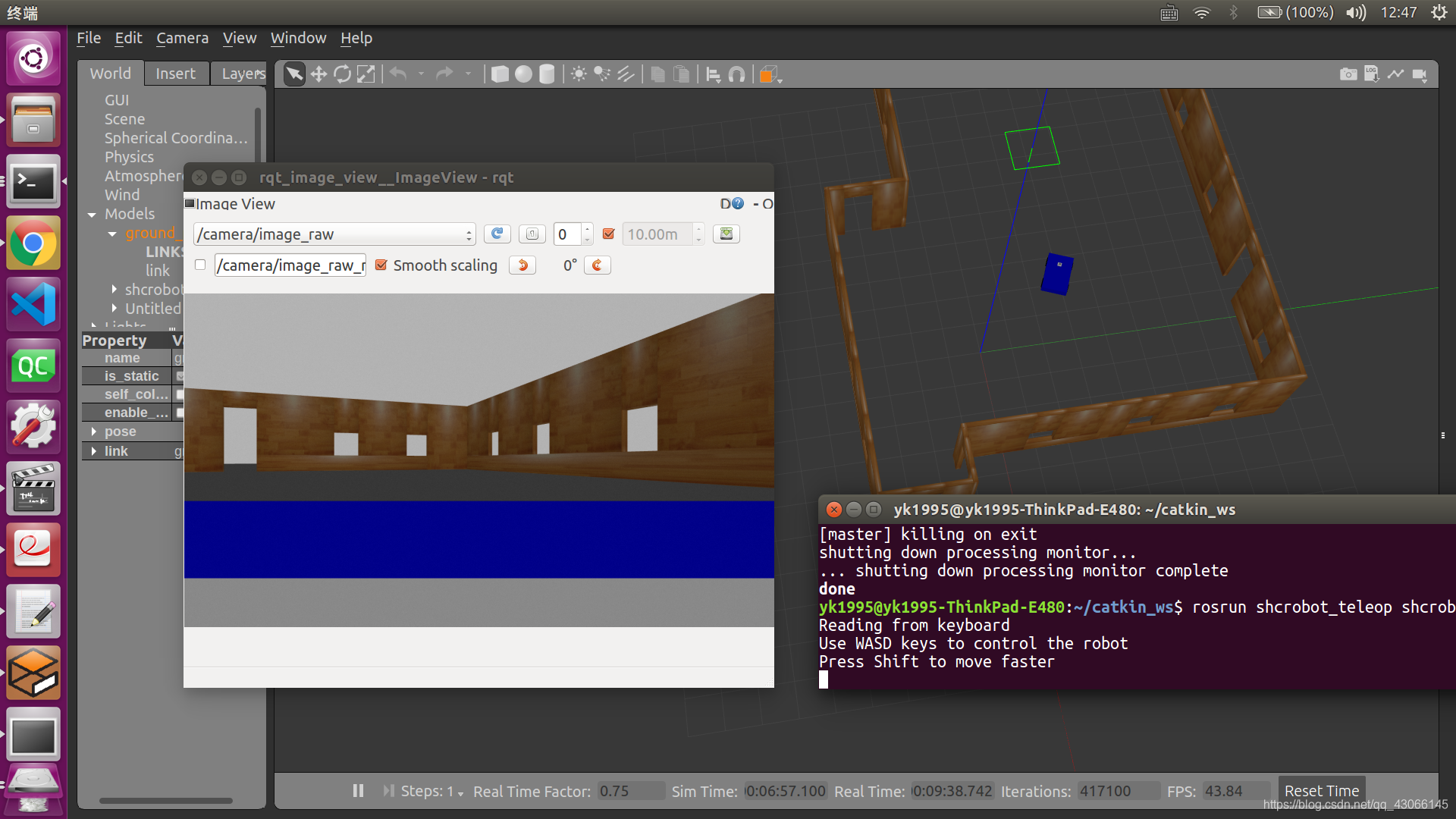
启动键盘控制节点和rqt_image_view节点,可以输出相机的画面
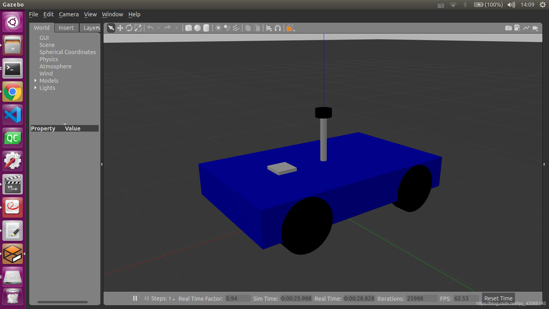
2.激光雷达
1.添加lidar_gazebo.xacro文件
<?xml version="1.0"?>
<robot xmlns:xacro="http://www.ros.org/wiki/xacro" name="laser">

    <xacro:macro name="rplidar" params="prefix:=laser">
        <!-- Create laser reference frame -->
        <link name="${prefix}_link">
            <inertial>
                <mass value="0.1" />
                <origin xyz="0 0 0" />
                <inertia ixx="0.01" ixy="0.0" ixz="0.0"
                         iyy="0.01" iyz="0.0"
                         izz="0.01" />
            </inertial>

            <visual>
                <origin xyz=" 0 0 0 " rpy="0 0 0" />
                <geometry>
                    <cylinder length="0.05" radius="0.05"/>
                </geometry>
                <material name="black"/>
            </visual>

            <collision>
                <origin xyz="0.0 0.0 0.0" rpy="0 0 0" />
                <geometry>
                    <cylinder length="0.06" radius="0.05"/>
                </geometry>
            </collision>
        </link>
        <gazebo reference="${prefix}_link">
            <material>Gazebo/Black</material>
        </gazebo>

        <gazebo reference="${prefix}_link">
            <sensor type="ray" name="rplidar">
                <pose>0 0 0 0 0 0</pose>
                <visualize>false</visualize>
                <update_rate>5.5</update_rate>
                <ray>
                    <scan>
                      <horizontal>
                        <samples>360</samples>
                        <resolution>1</resolution>
                        <min_angle>-3</min_angle>
                        <max_angle>3</max_angle>
                      </horizontal>
                    </scan>
                    <range>
                      <min>0.10</min>
                      <max>6.0</max>
                      <resolution>0.01</resolution>
                    </range>
                    <noise>
                      <type>gaussian</type>
                      <mean>0.0</mean>
                      <stddev>0.01</stddev>
                    </noise>
                </ray>
                <plugin name="gazebo_rplidar" filename="libgazebo_ros_laser.so">
                    <topicName>/scan</topicName>
                    <frameName>laser_link</frameName>
                </plugin>
            </sensor>
        </gazebo>

    </xacro:macro>
</robot>
2.调用lidar_gazebo.xacro文件生成总模型shcRobot2_xacro_lida_gazebo.xacro
<?xml version="1.0"?>
<robot name="arm" xmlns:xacro="http://www.ros.org/wiki/xacro">
    <xacro:include filename="$(find shcrobot_description)/urdf/xacro/shcRobot2_base_lida_gazebo.xacro"/>
    <xacro:include filename="$(find shcrobot_description)/urdf/xacro/lidar_gazebo.xacro"/>

    <xacro:property name="lidar_offset_x" value="0" />
    <xacro:property name="lidar_offset_y" value="0" />
    <xacro:property name="lidar_offset_z" value="0.4" />

    <robot_base/>

    <!-- lidar -->
    <joint name="lidar_joint" type="fixed">
        <origin xyz="${lidar_offset_x} ${lidar_offset_y} ${lidar_offset_z}" rpy="0 0 0" />
        <parent link="base_link"/>
        <child link="laser_link"/>
    </joint>

    <xacro:rplidar prefix="laser"/>

</robot>
大家注意一下,上面的文件中,使用的是shcRobot2_base_lida_gazebo.xacro作为小车的基础模型,和之前的shcRobot2_base_gazebo.xacro不太一样,其实就是添加了支撑雷达的杆,为了方便起见,还是把代码粘在下面
<?xml version="1.0"?>
<robot name="robot" xmlns:xacro="http://www.ros.org/wiki/xacro">
<xacro:property name="M_PI"        value="3.14159"/>
<xacro:property name="base_length" value="1.3"/>
<xacro:property name="base_width"  value="0.8"/>
<xacro:property name="base_height" value="0.2"/>
<xacro:property name="base_mass"   value="10"/>
<xacro:property name="head_mass"   value="0.2"/>

<xacro:property name="wheel_length" value="0.08"/>
<xacro:property name="wheel_radius" value="0.15"/>
<xacro:property name="wheel_mass"   value="1"/>

<xacro:property name="wheel_x_offset"    value="0.4"/>
<xacro:property name="wheel_y_offset"    value="0.375"/>
<xacro:property name="wheel_z_offset"    value="-0.055"/>

<material name="yellow">
	<color rgba="1 0.4 0 1"/>
</material>
<material name="black">
	<color rgba="0 0 0 0.9"/>
</material>
<material name="gray">
	<color rgba="0.75 0.75 0.75 1"/>
</material>
<material name="white">
	<color rgba="1 1 1 1"/>
</material>
<material name="blue">
        <color rgba="0 0 .8 1"/>
</material>

<xacro:macro name="cylinder_inertial_matrix" params="m r h">
	<inertial>
		<mass value="${m}"/>
		<inertia ixx="${m*(3*r*r+h*h)/12}" ixy="0" ixz="0" iyy="${m*(3*r*r+h*h)/12}" iyz="0" izz="${m*r*r/2}"/>
	</inertial>
</xacro:macro>

<xacro:macro name="retangle_inertial_matrix" params="m d w h">
	<inertial>
		<mass value="${m}"/>
		<inertia ixx="${m*(d*d+h*h)/12}" ixy="0" ixz="0" iyy="${m*(d*d+w*w)/12}" iyz="0" izz="${m*(h*h+w*w)/12}"/>
	</inertial>
</xacro:macro>

<xacro:macro name="steer_wheel" params="prefix reflect">

    <link name="${prefix}_front_wheel">
    	<visual>
	    <origin xyz="0 0 0" rpy="${M_PI/2} 0 0"/>
	    <geometry>
		<cylinder length="${wheel_length}" radius="${wheel_radius}"/>
	    </geometry>
	    <material name="black"/>
        </visual>
	<collision>
	    <origin xyz="0 0 0" rpy="${M_PI/2} 0 0"/>
	    <geometry>
	    <cylinder length="${wheel_length}" radius="${wheel_radius}"/>
	    </geometry>
	</collision>
	<cylinder_inertial_matrix m="${wheel_mass}" r="${wheel_radius}" h="${wheel_length}"/>
    </link>

    <joint name="${prefix}_front_steer_joint"  type="continuous">
	<origin xyz="${wheel_x_offset} ${reflect*wheel_y_offset} ${wheel_z_offset}" rpy="0 0 0"/>
	<parent link="base_link"/>
	<child  link="${prefix}_front_wheel"/>
	<axis   xyz="0 1 0"/>
    </joint>
    <gazebo reference="${prefix}_front_wheel">
        <material>Gazebo/Black</material>
    </gazebo>
        <transmission name="${prefix}_wheel_joint_trans">
            <type>transmission_interface/SimpleTransmission</type>
            <joint name="${prefix}_front_steer_joint" >
                <hardwareInterface>hardware_interface/VelocityJointInterface</hardwareInterface>
            </joint>
            <actuator name="${prefix}_wheel_joint_motor">
                <hardwareInterface>hardware_interface/VelocityJointInterface</hardwareInterface>
                <mechanicalReduction>1</mechanicalReduction>
            </actuator>
        </transmission>
</xacro:macro>

<xacro:macro name="drive_wheel" params="prefix reflect">

    <link name="${prefix}_rear_wheel">
    	<visual>
	    <origin xyz="0 0 0" rpy="${M_PI/2} 0 0"/>
	    <geometry>
		<cylinder length="${wheel_length}" radius="${wheel_radius}"/>
	    </geometry>
	    <material name="black"/>
        </visual>
	<collision>
	    <origin xyz="0 0 0" rpy="${M_PI/2} 0 0"/>
	    <geometry>
	    <cylinder length="${wheel_length}" radius="${wheel_radius}"/>
	    </geometry>
	</collision>
	<cylinder_inertial_matrix m="${wheel_mass}" r="${wheel_radius}" h="${wheel_length}"/>
    </link>

    <joint name="${prefix}_rear_drive_joint"  type="continuous">
	<origin xyz="${-1*wheel_x_offset} ${reflect*wheel_y_offset} ${wheel_z_offset}" rpy="0 0 0"/>
	<parent link="base_link"/>
	<child  link="${prefix}_rear_wheel"/>
	<axis   xyz="0 1 0"/>
    </joint>
    <gazebo reference="${prefix}_rear_wheel">
        <material>Gazebo/Black</material>
    </gazebo>

        <transmission name="${prefix}_wheel_joint_trans">
            <type>transmission_interface/SimpleTransmission</type>
            <joint name="${prefix}_rear_drive_joint" >
                <hardwareInterface>hardware_interface/VelocityJointInterface</hardwareInterface>
            </joint>
            <actuator name="${prefix}_wheel_joint_motor">
                <hardwareInterface>hardware_interface/VelocityJointInterface</hardwareInterface>
                <mechanicalReduction>1</mechanicalReduction>
            </actuator>
        </transmission>
</xacro:macro>

<xacro:macro name="robot_base">

    <link name="head">
    	<visual>
	    <origin xyz="0 0 0" rpy="0 0 0"/>
	    <geometry>
		<box size=".12 .13 .04"/>
	    </geometry>
	    <material name="white"/>
        </visual>
	<collision>
	    <origin xyz="0 0 0" rpy="0 0 0"/>
	    <geometry>
	    <box size=".12 .13 .04"/>
	    </geometry>
	</collision>
	<retangle_inertial_matrix m="${head_mass}" d=".12" w=".13" h=".04"/>
    </link>
    <gazebo reference="head">
        <material>Gazebo/White</material>
    </gazebo>
    <joint name="tobox"  type="fixed">
	<origin xyz="0.3 0 0.1" rpy="0 0 0"/>
	<parent link="base_link"/>
	<child  link="head"/>
    </joint>


    <link name="lida_rod">
    	<visual>
	    <origin xyz="0 0 0" rpy="0 0 0"/>
	    <geometry>
		<cylinder length=".4" radius=".02"/>
	    </geometry>
	    <material name="white"/>
        </visual>
	<collision>
	    <origin xyz="0 0 0" rpy="0 0 0"/>
	    <geometry>
	    <cylinder length=".4" radius=".02"/>
	    </geometry>
	</collision>
	<cylinder_inertial_matrix m=".3" r=".02" h=".4"/>
    </link>
    <gazebo reference="lida_road">
        <material>Gazebo/Gray</material>
    </gazebo>
    <joint name="tobox2"  type="fixed">
	<origin xyz="0 0 0.2" rpy="0 0 0"/>
	<parent link="base_link"/>
	<child  link="lida_rod"/>
    </joint>


    <link name="base_link">
      <visual>
        <geometry>
          <box size="${base_length} ${base_width} ${base_height}"/>
        </geometry>
        <origin rpy="0 0 0" xyz="0 0 0"/>
        <material name="blue"/>
      </visual>
      <collision>
	<geometry>
        <box size="${base_length} ${base_width} ${base_height}"/>
        </geometry>
        <origin rpy="0 0 0" xyz="0 0 0"/>
      </collision>
      <retangle_inertial_matrix m="${base_mass}" d="${base_length}" w="${base_width}" h="${base_height}"/>
    </link>

    <gazebo reference="base_link">
	<material>Gazebo/Blue</material>
    </gazebo>

    <steer_wheel prefix="left"  reflect="1"/>
    <steer_wheel prefix="right" reflect="-1"/>
    <drive_wheel prefix="left"  reflect="1"/>
    <drive_wheel prefix="right" reflect="-1"/>

        <gazebo>
            <plugin name="differential_drive_controller"
                    filename="libgazebo_ros_diff_drive.so">
                <rosDebugLevel>Debug</rosDebugLevel>
                <publishWheelTF>true</publishWheelTF>
                <robotNamespace>/</robotNamespace>
                <publishTf>1</publishTf>
                <publishWheelJointState>true</publishWheelJointState>
                <alwaysOn>true</alwaysOn>
                <updateRate>100.0</updateRate>
                <legacyMode>true</legacyMode>
                <leftJoint>left_rear_drive_joint</leftJoint>
                <rightJoint>right_rear_drive_joint</rightJoint>
                <wheelSeparation>0.8</wheelSeparation>
                <wheelDiameter>${2*wheel_radius}</wheelDiameter>
                <broadcastTF>1</broadcastTF>
                <wheelTorque>80</wheelTorque>
                <wheelAcceleration>3</wheelAcceleration>
                <commandTopic>cmd_vel</commandTopic>
                <odometryFrame>odom</odometryFrame>
                <odometryTopic>odom</odometryTopic>
                <robotBaseFrame>base_link</robotBaseFrame>
            </plugin>
        </gazebo>
        <gazebo>
            <plugin name="differential_drive_controller"
                    filename="libgazebo_ros_diff_drive.so">
                <rosDebugLevel>Debug</rosDebugLevel>
                <publishWheelTF>true</publishWheelTF>
                <robotNamespace>/</robotNamespace>
                <publishTf>1</publishTf>
                <publishWheelJointState>true</publishWheelJointState>
                <alwaysOn>true</alwaysOn>
                <updateRate>100.0</updateRate>
                <legacyMode>true</legacyMode>
                <leftJoint>left_front_steer_joint</leftJoint>
                <rightJoint>right_front_steer_joint</rightJoint>
                <wheelSeparation>0.8</wheelSeparation>
                <wheelDiameter>${2*wheel_radius}</wheelDiameter>
                <broadcastTF>1</broadcastTF>
                <wheelTorque>80</wheelTorque>
                <wheelAcceleration>3</wheelAcceleration>
                <commandTopic>cmd_vel</commandTopic>
                <odometryFrame>odom</odometryFrame>
                <odometryTopic>odom</odometryTopic>
                <robotBaseFrame>base_link</robotBaseFrame>
            </plugin>
        </gazebo>
</xacro:macro>
</robot>
3.修改相应launch文件,启动仿真
<launch>
	<!-- 设置launch文件的参数 -->
    <arg name="paused" default="false"/>
    <arg name="use_sim_time" default="true"/>
    <arg name="gui" default="true"/>
    <arg name="headless" default="false"/>
    <arg name="debug" default="false"/>

	<!--运行gazebo仿真环境-->
	<include file="$(find gazebo_ros)/launch/empty_world.launch">
		<arg name="world_name" value="/home/yk1995/building_editor_models/world1/world2"/>
        	<arg name="debug" value="$(arg debug)" />
        	<arg name="gui" value="$(arg gui)" />
        	<arg name="paused" value="$(arg paused)"/>
        	<arg name="use_sim_time" value="$(arg use_sim_time)"/>
        	<arg name="headless" value="$(arg headless)"/>
    	</include>

	<!-- 加载机器人模型描述参数 -->
	<param name="robot_description" command="$(find xacro)/xacro --inorder '$(find shcrobot_description)/urdf/xacro/shcRobot2_xacro_lida_gazebo.xacro'"/>
	<!--运行joint_state_publisher节点,发布机器人关节状态-->
	<node name = "robot_state_publisher" pkg = "robot_state_publisher" type = "state_publisher">
		<param name="publish_frequency" type="double" value="20.0" />
	</node>
	    <!-- 在gazebo中加载机器人模型-->
    <node name="urdf_spawner" pkg="gazebo_ros" type="spawn_model" respawn="false" output="screen"
          args="-urdf -model shcrobot -param robot_description"/>

	<node pkg="tf" type="static_transform_publisher" name="link1_broadcaster" args="0.20 0 0 0 0 0 base_link laser 50" />

</launch>
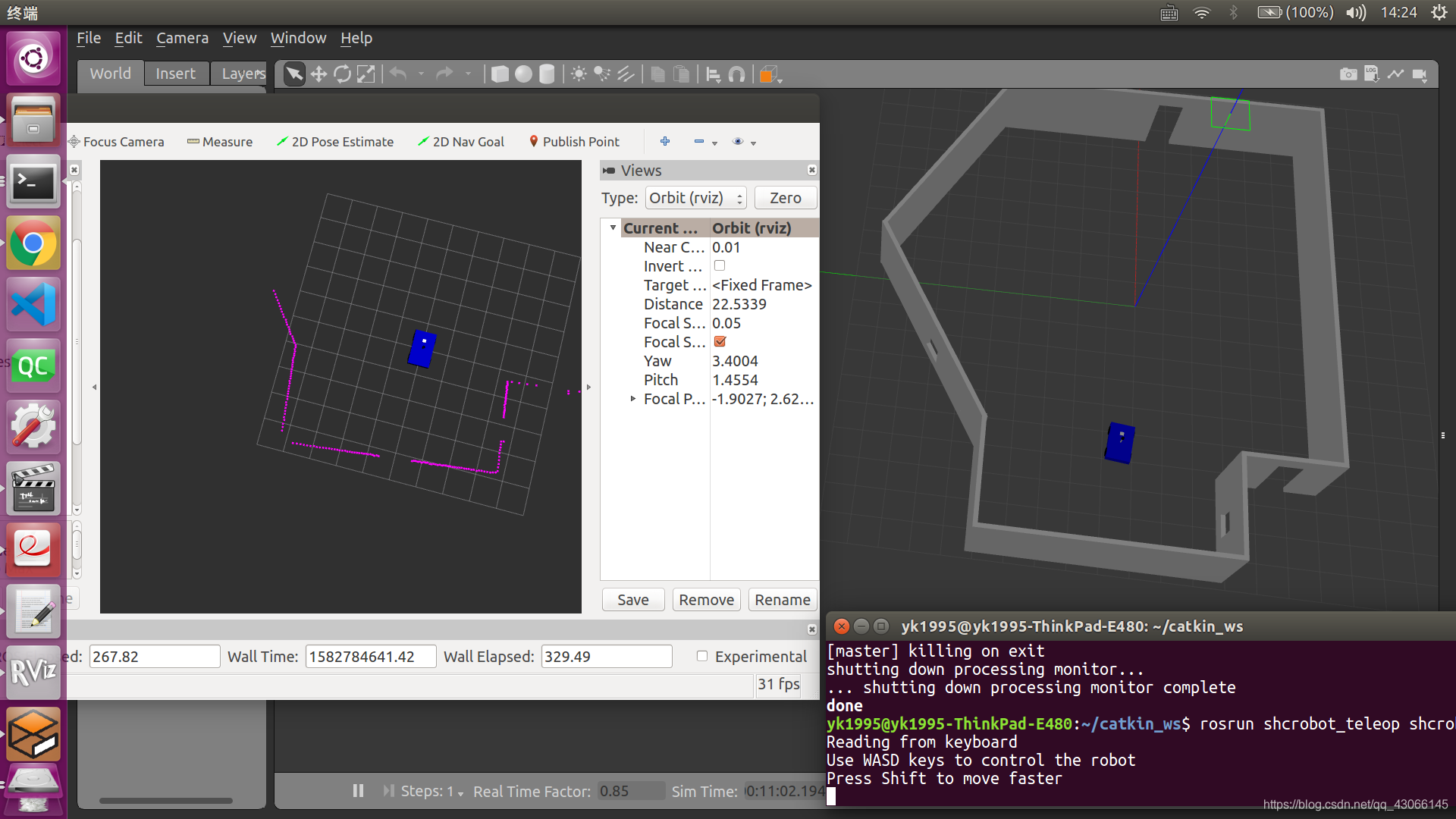
启动键盘控制节点和rviz节点,可以输出激光雷达的点云图像
附键盘控制节点的cpp文件[2]
#include <termios.h>
#include <signal.h>
#include <math.h>
#include <stdio.h>
#include <stdlib.h>
#include <sys/poll.h>

#include <boost/thread/thread.hpp>
#include <ros/ros.h>
#include <geometry_msgs/Twist.h>

#define KEYCODE_W 0x77
#define KEYCODE_A 0x61
#define KEYCODE_S 0x73
#define KEYCODE_D 0x64

#define KEYCODE_A_CAP 0x41
#define KEYCODE_D_CAP 0x44
#define KEYCODE_S_CAP 0x53
#define KEYCODE_W_CAP 0x57

class SmartCarKeyboardTeleopNode
{
    private:
        double walk_vel_;
        double run_vel_;
        double yaw_rate_;
        double yaw_rate_run_;

        geometry_msgs::Twist cmdvel_;
        ros::NodeHandle n_;
        ros::Publisher pub_;

    public:
        SmartCarKeyboardTeleopNode()
        {
            pub_ = n_.advertise<geometry_msgs::Twist>("cmd_vel", 2);

            ros::NodeHandle n_private("~");
            n_private.param("walk_vel", walk_vel_, 2.5);
            n_private.param("run_vel", run_vel_, 2.0);
            n_private.param("yaw_rate", yaw_rate_, 3.0);
            n_private.param("yaw_rate_run", yaw_rate_run_, 3.5);
        }
        ~SmartCarKeyboardTeleopNode() { }
        void keyboardLoop();

        void stopRobot()
        {
            cmdvel_.linear.x = 0.0;
            cmdvel_.angular.z = 0.0;
            pub_.publish(cmdvel_);
        }
};

SmartCarKeyboardTeleopNode* tbk;
int kfd = 0;
struct termios cooked, raw;
bool done;

int main(int argc, char** argv)
{
    ros::init(argc,argv,"tbk", ros::init_options::AnonymousName | ros::init_options::NoSigintHandler);
    SmartCarKeyboardTeleopNode tbk;

    boost::thread t = boost::thread(boost::bind(&SmartCarKeyboardTeleopNode::keyboardLoop, &tbk));

    ros::spin();
    t.interrupt();
    t.join();
    tbk.stopRobot();
    tcsetattr(kfd, TCSANOW, &cooked);

    return(0);
}

void SmartCarKeyboardTeleopNode::keyboardLoop()
{
    char c;
    double max_tv = walk_vel_;
    double max_rv = yaw_rate_;
    bool dirty = false;
    int speed = 0;
    int turn = 0;

    // get the console in raw mode
    tcgetattr(kfd, &cooked);
    memcpy(&raw, &cooked, sizeof(struct termios));
    raw.c_lflag &=~ (ICANON | ECHO);
    raw.c_cc[VEOL] = 1;
    raw.c_cc[VEOF] = 2;
    tcsetattr(kfd, TCSANOW, &raw);
    puts("Reading from keyboard");
    puts("Use WASD keys to control the robot");
    puts("Press Shift to move faster");

    struct pollfd ufd;
    ufd.fd = kfd;
    ufd.events = POLLIN;

    for(;;)
    {
        boost::this_thread::interruption_point();

        // get the next event from the keyboard
        int num;

        if ((num = poll(&ufd, 1, 250)) < 0)
        {
            perror("poll():");
            return;
        }
        else if(num > 0)
        {
            if(read(kfd, &c, 1) < 0)
            {
                perror("read():");
                return;
            }
        }
        else
        {
            if (dirty == true)
            {
                stopRobot();
                dirty = false;
            }

            continue;
        }

        switch(c)
        {
            case KEYCODE_W:
                max_tv = walk_vel_;
                speed = 1;
                turn = 0;
                dirty = true;
                break;
            case KEYCODE_S:
                max_tv = walk_vel_;
                speed = -1;
                turn = 0;
                dirty = true;
                break;
            case KEYCODE_A:
                max_rv = yaw_rate_;
                speed = 0;
                turn = 1;
                dirty = true;
                break;
            case KEYCODE_D:
                max_rv = yaw_rate_;
                speed = 0;
                turn = -1;
                dirty = true;
                break;

            case KEYCODE_W_CAP:
                max_tv = run_vel_;
                speed = 1;
                turn = 0;
                dirty = true;
                break;
            case KEYCODE_S_CAP:
                max_tv = run_vel_;
                speed = -1;
                turn = 0;
                dirty = true;
                break;
            case KEYCODE_A_CAP:
                max_rv = yaw_rate_run_;
                speed = 0;
                turn = 1;
                dirty = true;
                break;
            case KEYCODE_D_CAP:
                max_rv = yaw_rate_run_;
                speed = 0;
                turn = -1;
                dirty = true;
                break;
            default:
                max_tv = walk_vel_;
                max_rv = yaw_rate_;
                speed = 0;
                turn = 0;
                dirty = false;
        }
        cmdvel_.linear.x = speed * max_tv;
        cmdvel_.angular.z = turn * max_rv;
        pub_.publish(cmdvel_);
    }
}
参考文献:
1.深蓝学院-ROS理论与实践
2.https://www.guyuehome.com/253


 749
749

 被折叠的 条评论
为什么被折叠?
被折叠的 条评论
为什么被折叠?
 到【灌水乐园】发言


