


前言
📢本系列将依托赵虚左老师的ROS课程,写下自己的一些心得与笔记。
📢课程链接:https://www.bilibili.com/video/BV1Ci4y1L7ZZ
📢讲义链接:http://www.autolabor.com.cn/book/ROSTutorials/index.html
📢 文章可能存在疏漏的地方,恳请大家指出。
1. 机器人运动控制以及里程计信息显示
1.1 ros_control 简介
保证 ROS 程序的可移植性
ros_control:是一组软件包,它包含了控制器接口,控制器管理器,传输和硬件接口。ros_control 是一套机器人控制的中间件,是一套规范,不同的机器人平台只要按照这套规范实现,那么就可以保证 与ROS 程序兼容,通过这套规范,实现了一种可插拔的架构设计,大大提高了程序设计的效率与灵活性。
1.2 运动控制实现流程(Gazebo)
承上,运动控制基本流程:
- 已经创建完毕的机器人模型,编写一个单独的 xacro 文件,为机器人模型添加传动装置以及控制器
- 将此文件集成进xacro文件
- 启动 Gazebo 并发布 /cmd_vel 消息控制机器人运动
1.2.1 为 joint 添加传动装置以及控制器
两轮差速配置
<robot name="my_car_move" xmlns:xacro="http://wiki.ros.org/xacro">

    <!-- 传动实现:用于连接控制器与关节 -->
    <xacro:macro name="joint_trans" params="joint_name">
        <!-- Transmission is important to link the joints and the controller -->
        <transmission name="${joint_name}_trans">
            <type>transmission_interface/SimpleTransmission</type>
            <joint name="${joint_name}">
                <hardwareInterface>hardware_interface/VelocityJointInterface</hardwareInterface>
            </joint>
            <actuator name="${joint_name}_motor">
                <hardwareInterface>hardware_interface/VelocityJointInterface</hardwareInterface>
                <mechanicalReduction>1</mechanicalReduction>
            </actuator>
        </transmission>
    </xacro:macro>

    <!-- 每一个驱动轮都需要配置传动装置 -->
    <xacro:joint_trans joint_name="left_wheel2base_link" />
    <xacro:joint_trans joint_name="right_wheel2base_link" />

    <!-- 控制器 -->
    <gazebo>
        <plugin name="differential_drive_controller" filename="libgazebo_ros_diff_drive.so">
            <rosDebugLevel>Debug</rosDebugLevel>
            <publishWheelTF>true</publishWheelTF>
            <robotNamespace>/</robotNamespace>
            <publishTf>1</publishTf>
            <publishWheelJointState>true</publishWheelJointState>
            <alwaysOn>true</alwaysOn>
            <updateRate>100.0</updateRate>
            <legacyMode>true</legacyMode>
            <leftJoint>left_wheel2base_link</leftJoint> <!-- 左轮 -->
            <rightJoint>right_wheel2base_link</rightJoint> <!-- 右轮 -->
            <wheelSeparation>${base_link_radius * 2}</wheelSeparation> <!-- 车轮间距 -->
            <wheelDiameter>${wheel_radius * 2}</wheelDiameter> <!-- 车轮直径 -->
            <broadcastTF>1</broadcastTF>
            <wheelTorque>30</wheelTorque>
            <wheelAcceleration>1.8</wheelAcceleration>
            <commandTopic>cmd_vel</commandTopic> <!-- 运动控制话题 -->
            <odometryFrame>odom</odometryFrame>
            <odometryTopic>odom</odometryTopic> <!-- 里程计话题 -->
            <robotBaseFrame>base_footprint</robotBaseFrame> <!-- 根坐标系 -->
        </plugin>
    </gazebo>

</robot>
依据驱动轮的xacro文件,将此处的joint名称改为驱动轮关节的名称.
<xacro:joint_trans joint_name="left_wheel2base_link" />
<xacro:joint_trans joint_name="right_wheel2base_link" />
同理,此处也要进行修改
            <leftJoint>left_wheel2base_link</leftJoint>
            <rightJoint>right_wheel2base_link</rightJoint>
车轮间距与车轮直径也需修改
         <wheelSeparation>${base_link_radius * 2}</wheelSeparation> <!-- 车轮间距 -->
            <wheelDiameter>${wheel_radius * 2}</wheelDiameter> <!-- 车轮直径 -->
1.2.2 xacro文件集成
<!-- 组合小车底盘与摄像头 -->
<robot name="my_car_camera" xmlns:xacro="http://wiki.ros.org/xacro">
    <xacro:include filename="my_head.urdf.xacro" />
    <xacro:include filename="my_base.urdf.xacro" />
    <xacro:include filename="my_camera.urdf.xacro" />
    <xacro:include filename="my_laser.urdf.xacro" />
    <xacro:include filename="move.urdf.xacro" />
</robot>
1.2.3 启动 gazebo并控制机器人运动
<launch>

    <!-- 将 Urdf 文件的内容加载到参数服务器 -->
    <param name="robot_description" command="$(find xacro)/xacro $(find demo02_urdf_gazebo)/urdf/xacro/my_base_camera_laser.urdf.xacro" />
    <!-- 启动 gazebo -->
    <include file="$(find gazebo_ros)/launch/empty_world.launch">
        <arg name="world_name" value="$(find demo02_urdf_gazebo)/worlds/hello.world" />
    </include>

    <!-- 在 gazebo 中显示机器人模型 -->
    <node pkg="gazebo_ros" type="spawn_model" name="model" args="-urdf -model mycar -param robot_description"  />
</launch>
2. 雷达信息仿真以及显示
雷达仿真基本流程:
- 已经创建完毕的机器人模型,编写一个单独的 xacro 文件,为机器人模型添加雷达配置;
- 将此文件集成进xacro文件;
- 启动 Gazebo,使用 Rviz 显示雷达信息。
2.1 新建 Xacro 文件,配置雷达传感器信息
<robot name="my_sensors" xmlns:xacro="http://wiki.ros.org/xacro">

  <!-- 雷达 -->
  <gazebo reference="laser">
    <sensor type="ray" name="rplidar">
      <pose>0 0 0 0 0 0</pose>   <!-- 雷达位姿xyz rpy -->
      <visualize>true</visualize>   <!-- 雷达是否可视化 -->
      <update_rate>5.5</update_rate>   <!-- 雷达频率 -->
      <ray>
        <scan>
          <horizontal>
            <samples>360</samples>   <!-- 雷达旋转一周采样线束 -->
            <resolution>1</resolution>   <!-- 雷达射线分辨率,360条射线中1条测距,减小计算量 -->
            <min_angle>-3</min_angle>   <!-- 雷达采样范围-3~+3 -->
            <max_angle>3</max_angle>
          </horizontal>
        </scan>
        <range>
          <min>0.10</min>   <!-- 雷达距离,小于0.10采样无效 -->
          <max>30.0</max>  <!-- 雷达距离,大于30.0采样无效 -->
          <resolution>0.01</resolution>  <!-- 雷达精度 -->
        </range>
        <noise>
          <type>gaussian</type>  <!-- 高斯噪音 -->
          <mean>0.0</mean>
          <stddev>0.01</stddev>
        </noise>
      </ray>
      <plugin name="gazebo_rplidar" filename="libgazebo_ros_laser.so">
        <topicName>/scan</topicName>
        <frameName>laser</frameName>
      </plugin>
    </sensor>
  </gazebo>

</robot>
重点:
  <gazebo reference="laser">

        <topicName>/scan</topicName>
        <frameName>laser</frameName>
2.2 xacro 文件集成
<!-- 组合小车底盘与传感器 -->
<robot name="my_car_camera" xmlns:xacro="http://wiki.ros.org/xacro">
    <xacro:include filename="my_head.urdf.xacro" />
    <xacro:include filename="my_base.urdf.xacro" />
    <xacro:include filename="my_camera.urdf.xacro" />
    <xacro:include filename="my_laser.urdf.xacro" />
    <xacro:include filename="move.urdf.xacro" />
    <!-- 雷达仿真的 xacro 文件 -->
    <xacro:include filename="my_sensors_laser.urdf.xacro" />
</robot>
2.3 启动仿真环境
gazebo的launch文件与之前一致
rviz的launch文件如下:
<launch>
    <param name="robot_description" command="$(find xacro)/xacro $(find  urdf02_gazebo)/urdf/xacro/car.urdf.xacro" />
    <!--启动rviz -->
    <node pkg = "rviz" type = "rviz" name="rviz" args="-d $(find urdf01_rviz)/config/demo01.rviz"/>
    <!-- 添加关节状态发布节点 -->
    <node pkg="joint_state_publisher" type="joint_state_publisher" name="joint_state_publisher" />
    <!-- 添加机器人状态发布节点 -->
    <node pkg="robot_state_publisher" type="robot_state_publisher" name="robot_state_publisher" />
</launch>
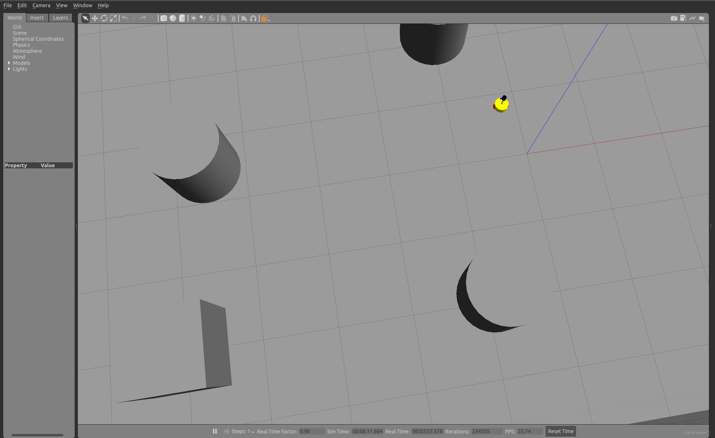
gazebo显示效果
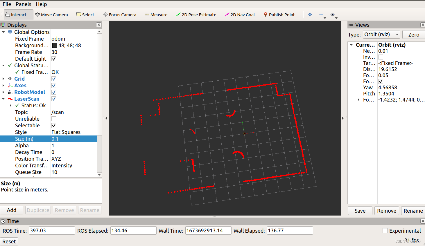
 rviz显示效果
3. 摄像头信息仿真以及显示
摄像头仿真基本流程:
- 已经创建完毕的机器人模型,编写一个单独的 xacro 文件,为机器人模型添加摄像头配置;
- 将此文件集成进xacro文件;
- 启动 Gazebo,使用 Rviz 显示摄像头信息。
3.1 新建 Xacro 文件,配置摄像头传感器信息
<robot name="my_sensors" xmlns:xacro="http://wiki.ros.org/xacro">
  <!-- 被引用的link -->
  <gazebo reference="camera">
    <!-- 类型设置为 camara -->
    <sensor type="camera" name="camera_node">
      <update_rate>30.0</update_rate> <!-- 更新频率 -->
      <!-- 摄像头基本信息设置 -->
      <camera name="head">
        <horizontal_fov>1.3962634</horizontal_fov>
        <image>
          <width>1280</width>
          <height>720</height>
          <format>R8G8B8</format>
        </image>
        <clip>
          <near>0.02</near>
          <far>300</far>
        </clip>
        <noise>
          <type>gaussian</type>
          <mean>0.0</mean>
          <stddev>0.007</stddev>
        </noise>
      </camera>
      <!-- 核心插件 -->
      <plugin name="gazebo_camera" filename="libgazebo_ros_camera.so">
        <alwaysOn>true</alwaysOn>
        <updateRate>0.0</updateRate>
        <cameraName>/camera</cameraName>
        <imageTopicName>image_raw</imageTopicName>
        <cameraInfoTopicName>camera_info</cameraInfoTopicName>
        <frameName>camera</frameName>
        <hackBaseline>0.07</hackBaseline>
        <distortionK1>0.0</distortionK1>
        <distortionK2>0.0</distortionK2>
        <distortionK3>0.0</distortionK3>
        <distortionT1>0.0</distortionT1>
        <distortionT2>0.0</distortionT2>
      </plugin>
    </sensor>
  </gazebo>
</robot>
重点
  <!-- 被引用的link -->
  <gazebo reference="camera">
    <!-- 类型设置为 camara -->
    <sensor type="camera" name="camera_node">

	<frameName>camera</frameName>
3.2 xacro 文件集成
<!-- 组合小车底盘与传感器 -->
<robot name="my_car_camera" xmlns:xacro="http://wiki.ros.org/xacro">
    <xacro:include filename="my_head.urdf.xacro" />
    <xacro:include filename="my_base.urdf.xacro" />
    <xacro:include filename="my_camera.urdf.xacro" />
    <xacro:include filename="my_laser.urdf.xacro" />
    <xacro:include filename="move.urdf.xacro" />
    <!-- 摄像头仿真的 xacro 文件 -->
    <xacro:include filename="my_sensors_camara.urdf.xacro" />
</robot>
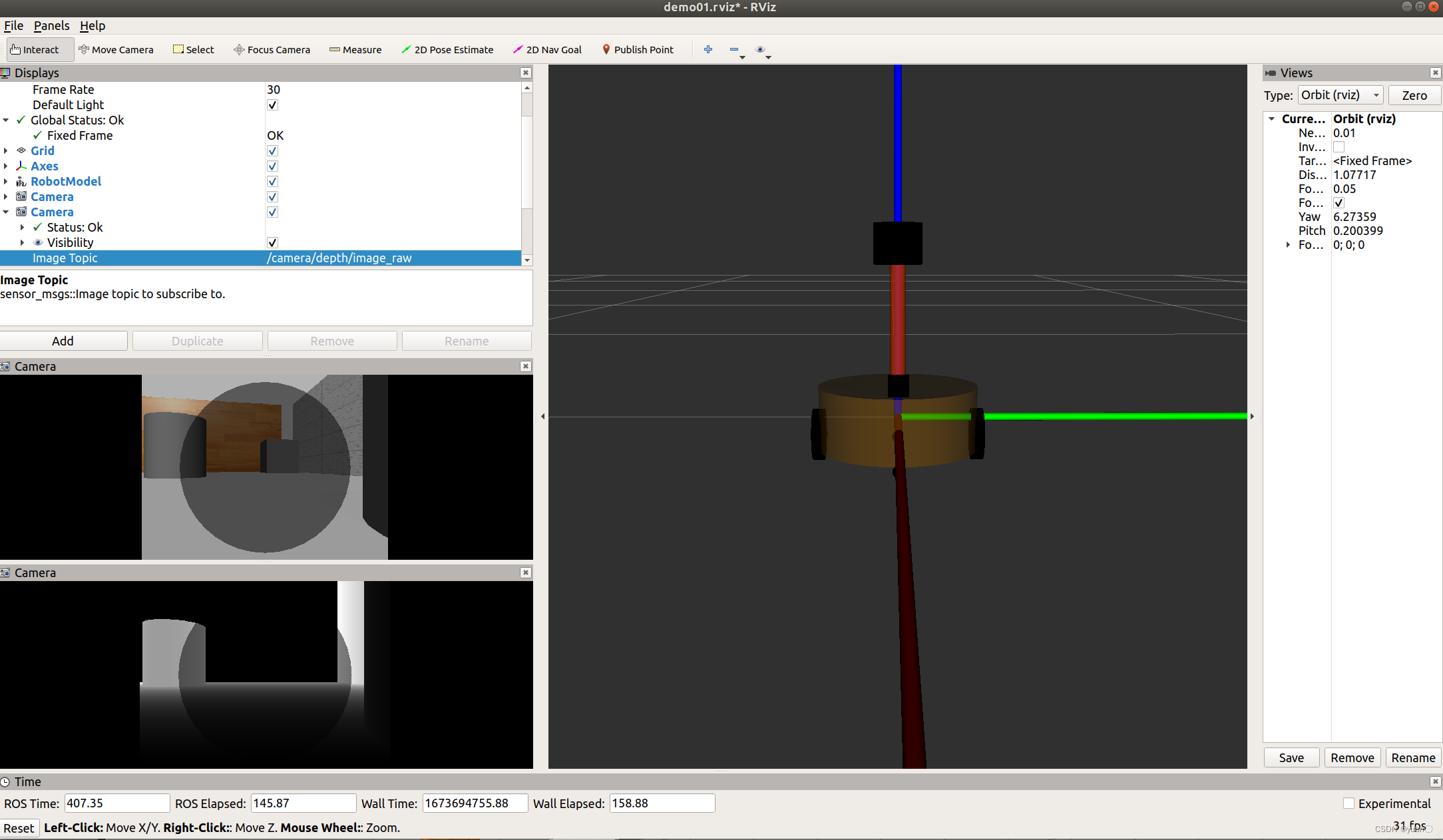
3.3 运行
和之前一致

4. kinect信息仿真以及显示
4.1 新建 Xacro 文件,配置 kinetic传感器信息
<robot name="my_sensors" xmlns:xacro="http://wiki.ros.org/xacro">
    <gazebo reference="kinect link名称">
      <sensor type="depth" name="camera">
        <always_on>true</always_on>
        <update_rate>20.0</update_rate>
        <camera>
          <horizontal_fov>${60.0*PI/180.0}</horizontal_fov>
          <image>
            <format>R8G8B8</format>
            <width>640</width>
            <height>480</height>
          </image>
          <clip>
            <near>0.05</near>
            <far>8.0</far>
          </clip>
        </camera>
        <plugin name="kinect_camera_controller" filename="libgazebo_ros_openni_kinect.so">
          <cameraName>camera</cameraName>
          <alwaysOn>true</alwaysOn>
          <updateRate>10</updateRate>
          <imageTopicName>rgb/image_raw</imageTopicName>
          <depthImageTopicName>depth/image_raw</depthImageTopicName>
          <pointCloudTopicName>depth/points</pointCloudTopicName>
          <cameraInfoTopicName>rgb/camera_info</cameraInfoTopicName>
          <depthImageCameraInfoTopicName>depth/camera_info</depthImageCameraInfoTopicName>
          <frameName>kinect link名称</frameName>
          <baseline>0.1</baseline>
          <distortion_k1>0.0</distortion_k1>
          <distortion_k2>0.0</distortion_k2>
          <distortion_k3>0.0</distortion_k3>
          <distortion_t1>0.0</distortion_t1>
          <distortion_t2>0.0</distortion_t2>
          <pointCloudCutoff>0.4</pointCloudCutoff>
        </plugin>
      </sensor>
    </gazebo>

</robot>
4.2 xacro 文件集成
<!-- 组合小车底盘与传感器 -->
<robot name="my_car_camera" xmlns:xacro="http://wiki.ros.org/xacro">
    <xacro:include filename="my_head.urdf.xacro" />
    <xacro:include filename="my_base.urdf.xacro" />
    <xacro:include filename="my_camera.urdf.xacro" />
    <xacro:include filename="my_laser.urdf.xacro" />
    <xacro:include filename="move.urdf.xacro" />
    <!-- kinect仿真的 xacro 文件 -->
    <xacro:include filename="my_sensors_kinect.urdf.xacro" />
</robot>
4.3 运行
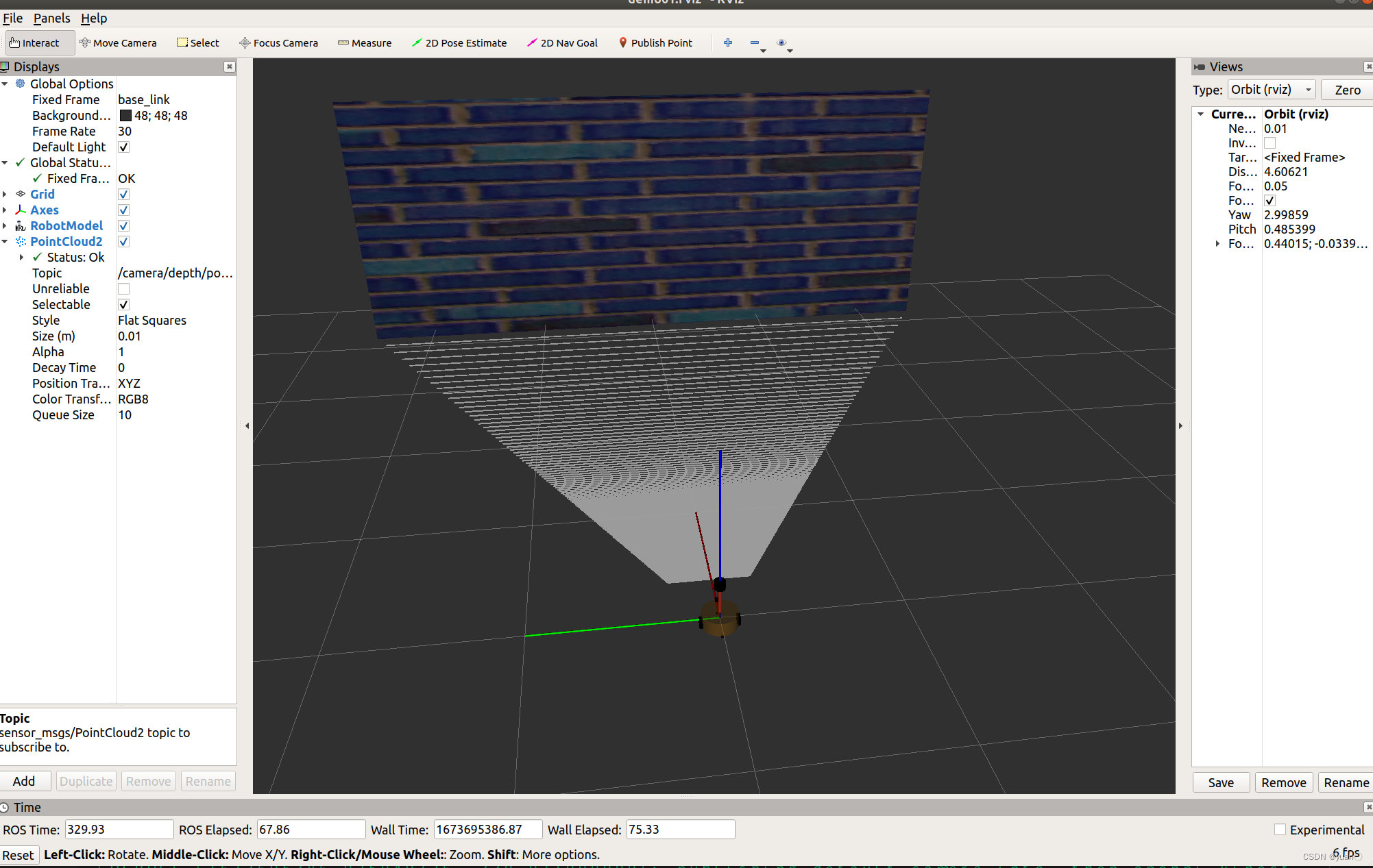
4.4 kinect 点云数据显示
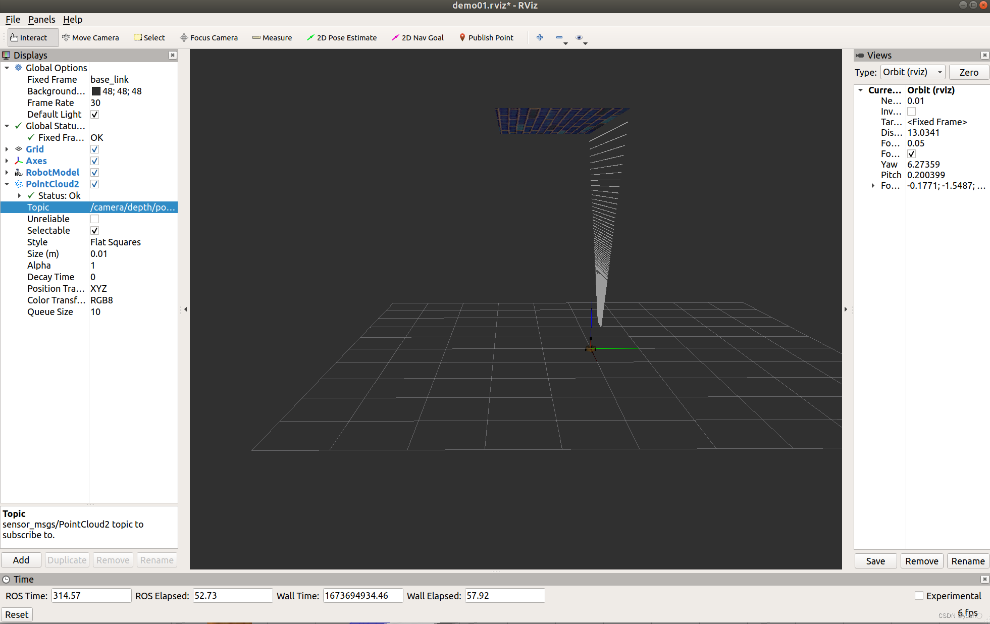
问题:在rviz中显示时错位。
原因:在kinect中图像数据与点云数据使用了两套坐标系统,且两套坐标系统位姿并不一致。
解决:
1.在插件中为kinect设置坐标系,修改配置文件的<frameName>标签内容:
<frameName>support_depth</frameName>
2.发布新设置的坐标系到kinect连杆的坐标变换关系,在启动rviz的launch中,添加:
<node pkg="tf2_ros" type="static_transform_publisher" name="static_transform_publisher" args="0 0 0 -1.57 0 -1.57 /support /support_depth" />


 3914
3914


 被折叠的 条评论
为什么被折叠?
被折叠的 条评论
为什么被折叠?
 到【灌水乐园】发言


