


模型編輯主要是自定義編輯物體模型構建環境,也可以將多種模型組合爲新模型等,支持外部模型導入,
需要注意的導入模型格式有相應要求,否在無法導入成功,
COLLADA (dae), STereoLithography (stl), Scalable Vector Graphics (svg)。
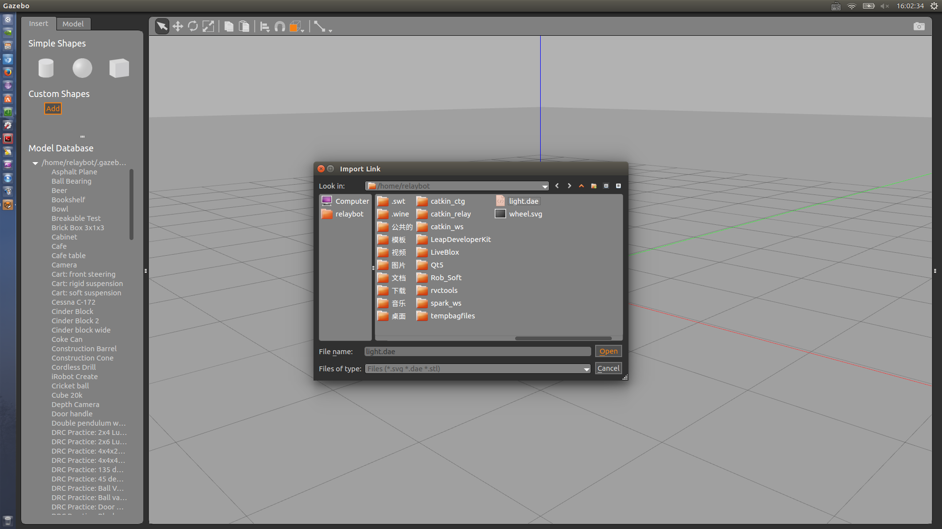
模型導入界面如下:
以Scalable Vector Graphics (svg)爲例,直接使用下面命令安裝使用:
~$ sudo apt-get install inkscape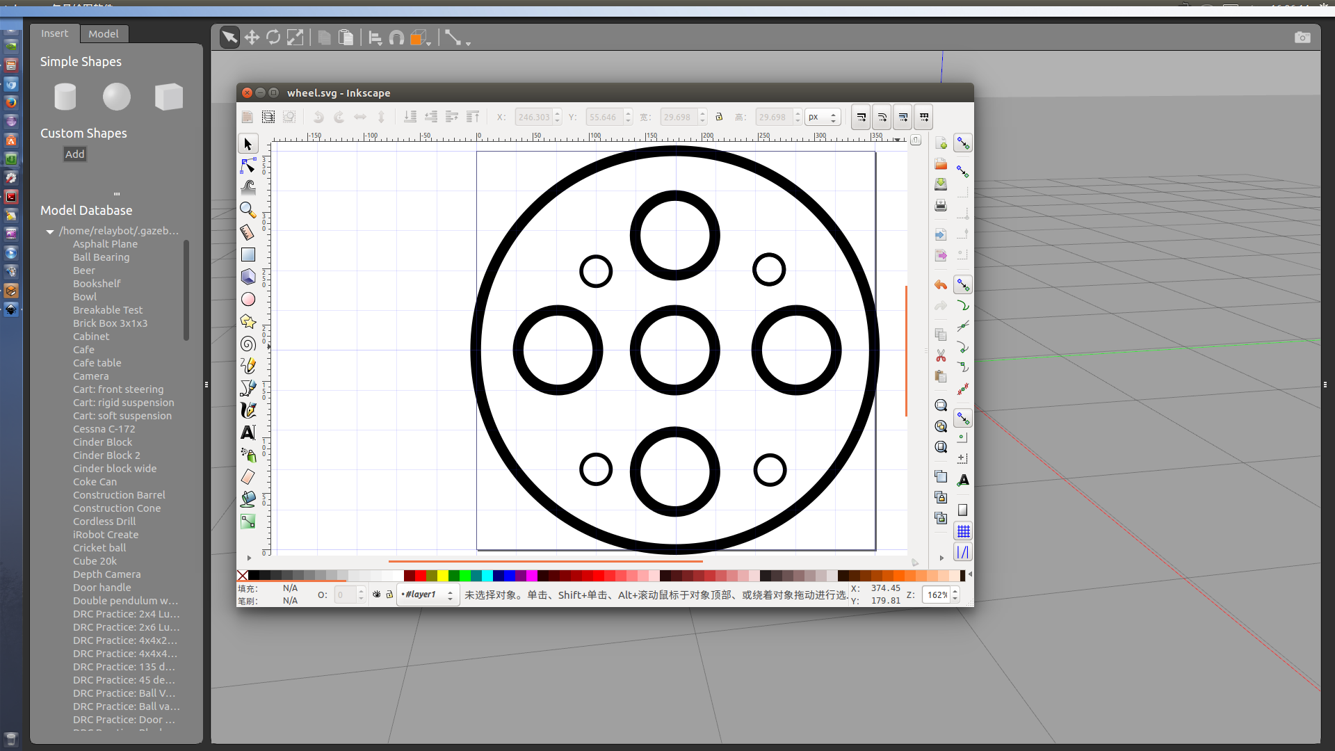
也可以編輯組合模型:
這部分內容都是可視化操作,簡潔易學,可直接參考附錄中的官方文檔。
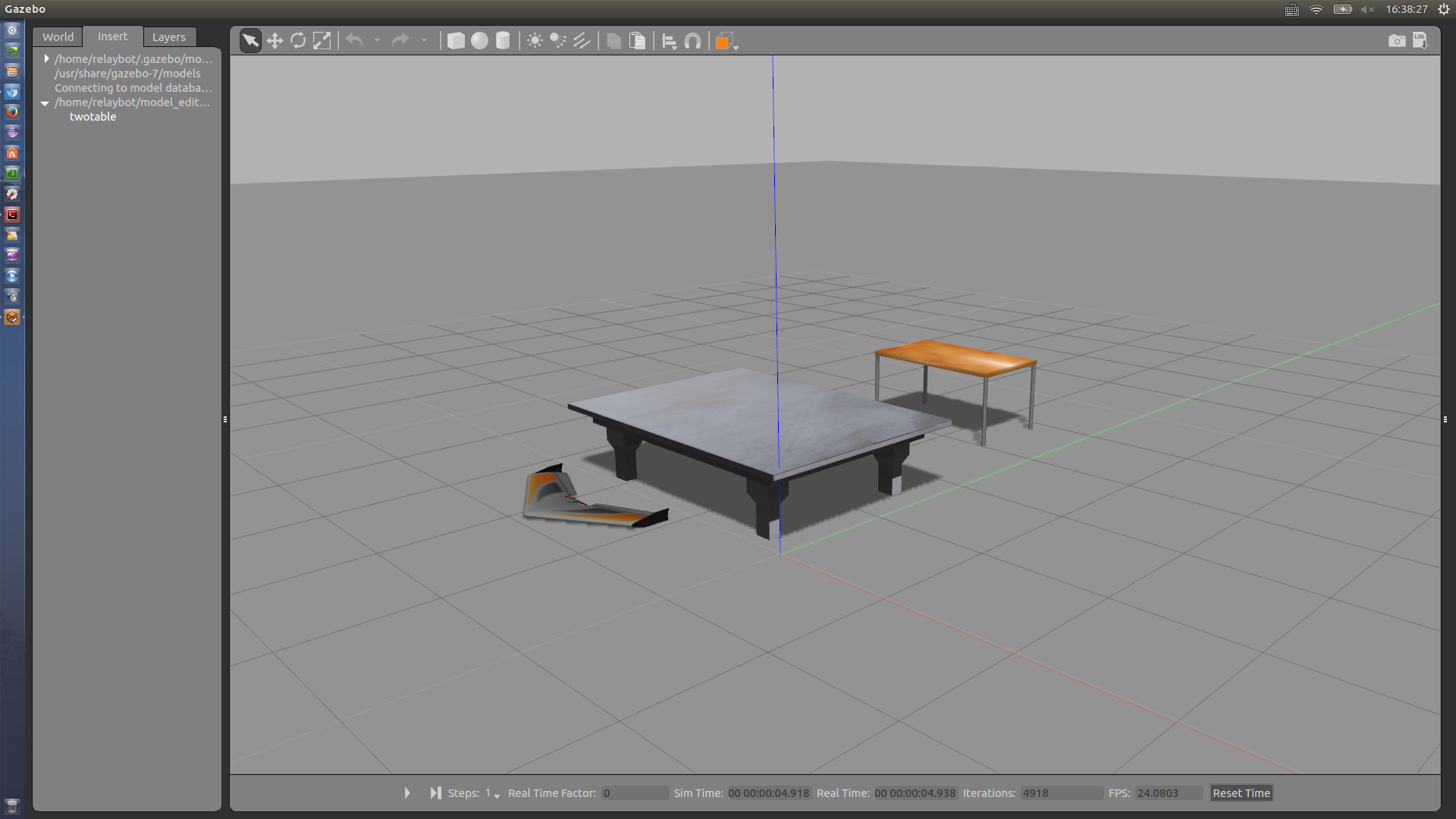
編輯好的模型可以重命名,然後另存,twotable,會自動生成如下文件。

效果如下:
自動生成的代碼如下所示:
model.config
<?xml version="1.0" ?>
<model>
    <name>twotable</name>
    <version>1.0</version>
    <sdf version="1.6">model.sdf</sdf>
    <author>
        <name></name>
        <email></email>
    </author>
    <description></description>
</model>
<?xml version='1.0'?>
<sdf version='1.6'>
  <model name='twotable'>
    <model name='table'>
      <static>0</static>
      <link name='link'>
        <collision name='surface'>
          <pose frame=''>0 0 1 0 -0 0</pose>
          <geometry>
            <box>
              <size>1.5 0.8 0.03</size>
            </box>
          </geometry>
          <surface>
            <friction>
              <ode>
                <mu>0.6</mu>
                <mu2>0.6</mu2>
              </ode>
            </friction>
          </surface>
        </collision>
        <visual name='visual1'>
          <pose frame=''>0 0 1 0 -0 0</pose>
          <geometry>
            <box>
              <size>1.4 0.8 0.04</size>
            </box>
          </geometry>
          <material>
            <script>
              <uri>file://media/materials/scripts/gazebo.material</uri>
              <name>Gazebo/Wood</name>
            </script>
          </material>
        </visual>
        <collision name='front_left_leg'>
          <pose frame=''>0.68 0.38 0.5 0 -0 0</pose>
          <geometry>
            <cylinder>
              <radius>0.02</radius>
              <length>1</length>
            </cylinder>
          </geometry>
        </collision>
        <visual name='front_left_leg'>
          <pose frame=''>0.68 0.38 0.5 0 -0 0</pose>
          <geometry>
            <cylinder>
              <radius>0.02</radius>
              <length>1</length>
            </cylinder>
          </geometry>
          <material>
            <script>
              <uri>file://media/materials/scripts/gazebo.material</uri>
              <name>Gazebo/Grey</name>
            </script>
          </material>
        </visual>
        <collision name='front_right_leg'>
          <pose frame=''>0.68 -0.38 0.5 0 -0 0</pose>
          <geometry>
            <cylinder>
              <radius>0.02</radius>
              <length>1</length>
            </cylinder>
          </geometry>
        </collision>
        <visual name='front_right_leg'>
          <pose frame=''>0.68 -0.38 0.5 0 -0 0</pose>
          <geometry>
            <cylinder>
              <radius>0.02</radius>
              <length>1</length>
            </cylinder>
          </geometry>
          <material>
            <script>
              <uri>file://media/materials/scripts/gazebo.material</uri>
              <name>Gazebo/Grey</name>
            </script>
          </material>
        </visual>
        <collision name='back_right_leg'>
          <pose frame=''>-0.68 -0.38 0.5 0 -0 0</pose>
          <geometry>
            <cylinder>
              <radius>0.02</radius>
              <length>1</length>
            </cylinder>
          </geometry>
        </collision>
        <visual name='back_right_leg'>
          <pose frame=''>-0.68 -0.38 0.5 0 -0 0</pose>
          <geometry>
            <cylinder>
              <radius>0.02</radius>
              <length>1</length>
            </cylinder>
          </geometry>
          <material>
            <script>
              <uri>file://media/materials/scripts/gazebo.material</uri>
              <name>Gazebo/Grey</name>
            </script>
          </material>
        </visual>
        <collision name='back_left_leg'>
          <pose frame=''>-0.68 0.38 0.5 0 -0 0</pose>
          <geometry>
            <cylinder>
              <radius>0.02</radius>
              <length>1</length>
            </cylinder>
          </geometry>
        </collision>
        <visual name='back_left_leg'>
          <pose frame=''>-0.68 0.38 0.5 0 -0 0</pose>
          <geometry>
            <cylinder>
              <radius>0.02</radius>
              <length>1</length>
            </cylinder>
          </geometry>
          <material>
            <script>
              <uri>file://media/materials/scripts/gazebo.material</uri>
              <name>Gazebo/Grey</name>
            </script>
          </material>
        </visual>
      </link>
      <pose frame=''>0 1.23981 -0.324 0 -0 0</pose>
    </model>
    <model name='table_marble'>
      <static>1</static>
      <pose frame=''>0 -1.23981 0.324 0 -0 0</pose>
      <link name='link'>
        <collision name='collision'>
          <geometry>
            <mesh>
              <uri>model:///table_marble/meshes/table_lightmap.dae</uri>
              <scale>0.25 0.25 0.25</scale>
            </mesh>
          </geometry>
        </collision>
        <visual name='visual'>
          <geometry>
            <mesh>
              <uri>model://table_marble/meshes/table_lightmap.dae</uri>
              <scale>0.25 0.25 0.25</scale>
            </mesh>
          </geometry>
          <material>
            <script>
              <uri>model://table_marble/materials/scripts</uri>
              <uri>model://table_marble/materials/textures</uri>
              <name>Table/Marble_Lightmap</name>
            </script>
            <lighting>0</lighting>
          </material>
        </visual>
      </link>
    </model>
    <static>0</static>
    <allow_auto_disable>1</allow_auto_disable>
  </model>
</sdf>附錄:官方文檔
Model Editor
Overview
This tutorial describes the process of creating a model using the Model Editor.
Open the Model Editor
Make sure Gazebo is installed.
Start up gazebo.
$ gazeboOn the
Editmenu, go toModel Editor, or hitCtrl+Mto open the editor.
Graphical user interface
The editor is composed of the following 2 areas:
The Palette on the left has two tabs. The
Inserttab lets you insertparts (links and other models) into the scene to build the model. TheModeltab displays a list of all the parts that make up the model you are building.The 3D View on the right where you can see a preview of your model andinteract with it to edit its properties and create joints between links.
The GUI tools on the top toolbar can be used to manipulate joints and links inthe 3D View.
Add Links
Add simple shapes
The model editor has three simple primitive geometries that the user can insertinto the 3D view to make a link of the model.
On the Palette, click on the
box,sphere, orcylindericon underSimple Shapes.Move your mouse cursor over the 3D view to see the visual appear, andclick/release anywhere to add it to the model.
Tip: You can press
Escto cancel adding the currentlink attached to the mouse cursor.
Add meshes
To add a custom mesh,
Click on the
Addbutton under Custom Shapes, which pops up a dialogthat lets you find the mesh you want to add.Click on
Browsebutton and use the file browser to find the mesh fileon your local machine. If you know the path of the mesh file, you can enter itdirectly in the text field box next to theBrowsebutton. Note Gazebocurrently only supports importing COLLADA (dae), STereoLithography (stl),and Scalable Vector Graphics (svg) files.Click
Importto load the mesh file. Then, add it to the 3D view.
Create Joints
The model editor supports creating several types of joints between links in themodel being edited. To create a joint:
Click on the
jointicon on the tool bar. This brings up the Joint CreationDialog which allows you to specify different properties of the joint youwant to create. As you can see in the dialog, the default joint type isaRevolutejoint.Begin by moving your mouse over the link you wish to create a joint for tosee it being highlighted and click on it. This link will be the parent link ofthe joint.
Next, move your mouse to the link which you would like to be the child linkof the joint. Click on it to see a colored line connecting the two links anda joint visual attached to the child link.

The line representing the joint is color-coded. Play around with differentjoint types to see the colors.
The joint visual consists of RGB axes which help to give an idea of thecoordinate frame of the joint. The yellow arrow indicates the primary axis ofthe joint. For example, in the case of a revolute joint, this is the axis ofrotation.
Once you have specified all the desired properties of the joint in theJoint Creation Dialog, click on the
Createbutton at the bottom to finalizejoint creation.Tip: You can press
Escany time to cancel the joint creation process.
Edit your model
Note: Be careful when editing your model; the editor currently has no option to undo your actions.
Tip: All measurements are in meters.
Edit links
The model editor supports editing properties of a link which you wouldalso find in its SDF.
Note: Gazebo 6+ supports editinglinks, visuals, and collisions. The ability to edit sensors andplugins are to be implemented in later versions.
To edit a link's properties: Double-click on the link or right click and selectOpen Link Inspector. A dialog window will appear which containsLink, Visual, and Collision property tabs.
As an example, try changing the link pose and visual colors. Once you are done, click onOK to close the inspector.

Edit joints
As mentioned earlier, joint properties can also be edited. These are propertiesthat you would find in the joint SDF.
To edit a joint: Double-click on the line connecting the links or right clickon it and select Open Joint Inspector. The joint inspector will appear.
As an example, try changing the joint pose and joint type. Once you are done, click onOK to close the inspector.

Saving your model
Saving will create a directory, SDF and config files for your model.
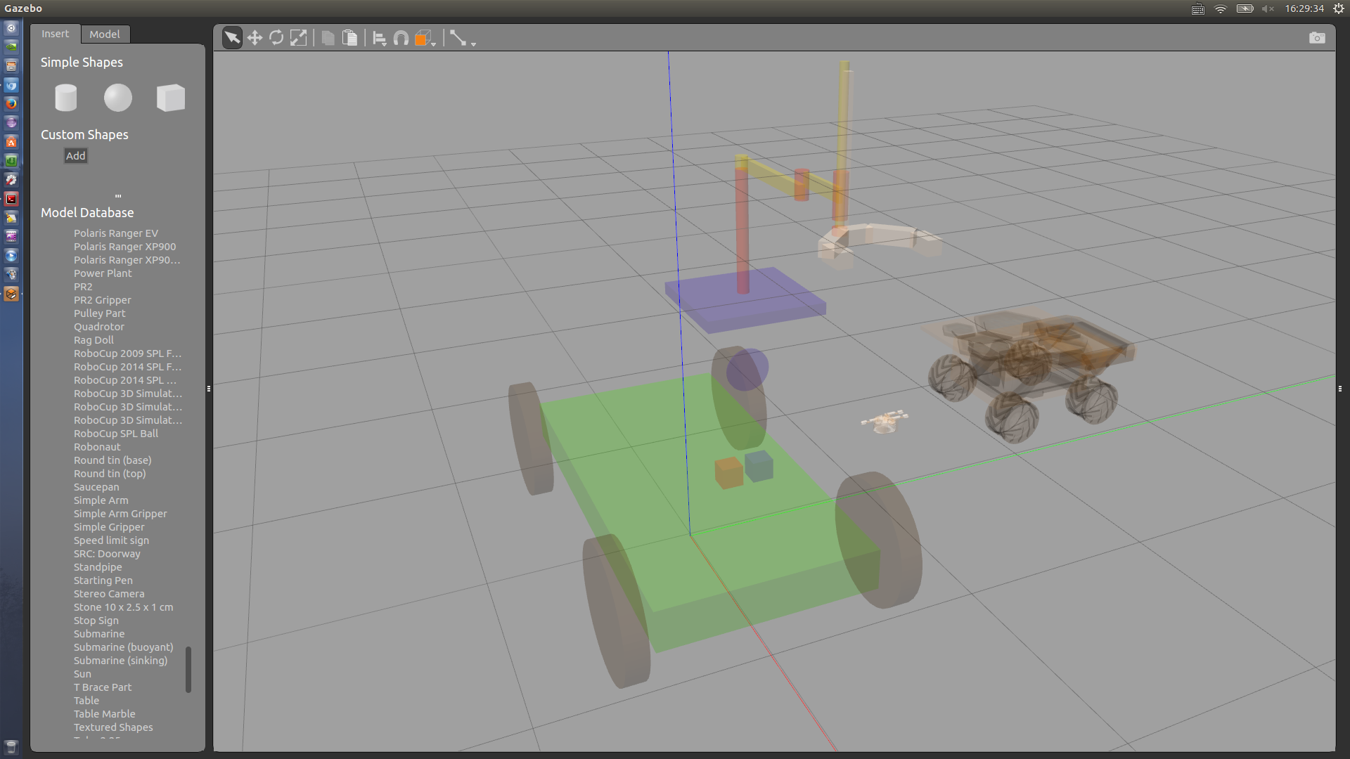
As an exercise, let's build a simple car and save it. The car will have abox chassis and four cylinder wheels. Each wheel will be connected to thechassis with a revolute joint:

Once you're happy with the model you created, go to the Model tab in the leftpanel and give it a name.

To save the model, choose File, then Save As (or hit Ctrl+S) in the topmenu. A dialog will come up where you can choose the location for your model.

Exit
When you're done creating the model and you've saved it, go to File and thenExit Model Editor.
Your model will show up in the main window.

Edit existing models
Rather than creating a model from the ground up;you can also edit existing models that are already in the simulation.
To edit an existing model:
Make sure you have saved the model you created, and you have exited the model editor. Alternatively, start from a fresh Gazebo instance.
Insert a model from the
Inserttab on the left. For example, let'sinsert aSimple Arm.Right click on the model you just inserted and select
Edit Model.
Now you are in the model editor and you are free to add new links to themodel or edit existing ones.
Extrude SVG files
Overview
This tutorial describes the process of extruding SVG files, which are 2Dimages, to create 3D meshes for your models in Gazebo. It is sometimeseasier to design part of a model in a program like Inkscape or Illustrator.
Before starting, make sure you're familiar with theModel Editor.
This tutorial will show you how to make a custom wheel as an .svg in Inkscape,and import it into Gazebo so that it can be attached to a robot.
Using the Inkscape SVG editor
![]()
There are many SVG editors. For this tutorial, we will use the open sourceInkscape program (seeinstallation instructions ).
This is the wheelSVG file used in this tutorial.

Document preparation
Start Inkscape. This will create a blank document. First, lets change thedocument size to better accommodate our wheel: under the File->Documentproperties menu, select the Page tab and change the document size to acustom size of 100.0 x 100.0 mm.

Then, in the same dialog, select the Gridstab, press the New button to create a custom grid. Then, check the Enabled,Visible, and Snap to visible grid lines only options. ChangeSpacing X and Spacing Y to be 10.

You should end up with a document looking like this:
![]()
Draw
You can use the different tools (pen, text, stars and shapes, etc.) to createyour geometry. In this example, the wheel is made from circles (pressing theShift Key you can start your circle from the center, and using the CTRL keyallows you to keep the roundness of the shape). It is possible to combineshapes together, making sure that paths are closed and that the part hasa proper thickness.
Note: a stick figure or two circles that touch each other would notresult in valid Gazebo models. The SVG paths must create an closed contour withholes, where the holes cannot touch the contour or other holes. Holes insideholes are treated as solid parts (and they can have holes, too).

Gazebo only imports paths, but it's easy with Inkscape to transform any shapeto a path. Select Select All from the Edit menu. Then select thePath -> Object to Path menu item. This will transform every object intoseparate paths and sub paths. This transformation is irreversible, so if youtransform text into paths, you will not be able to alter the text.

Gazebo does not support grouping. Use the Ungroup from the Object menu toseparate groups of paths.
Save your drawing
Save your drawing to an SVG file you can use later in Gazebo. Use the Saveoption from the File menu.
Create a Gazebo Model
SDFormat does not support SVG directly; it supports 2Dpoly lines. The Gazebo Model Editor has an import mechanism that extracts thepoly lines from SVG files, and saves them as an SDF model file.
Launch Gazebo and Select Model Editor from the Edit menu to enter theGazebo Model Editor mode (as opposed to the simulation mode).
Then press the Add button in the Custom Shapes section of the Insert tab.

This will open the Import Link dialog from where you can select the SVG fileby pressing the Browse button.

Once the file has been selected, press the Import button to open theExtrude Link dialog.

The dialog allows you to set parameters of the extrusions:
Thickness: How thick the link will be. This corresponds to the extrusionheight in the
zaxis. For the SVG path shown on the right, the axis ofextrusion is outwards from the screen.Resolution: How many pixels in your SVG correspond to a meter. Thedefault value (3543.3 px/m) corresponds to 90 dpi (dots per inch), which isthe default resolution for several editors, including Inkscape. If your modelshows up the size you'd like in Inkscape when you display the units as meters,you shouldn't change the resolution value.
Samples per segment: This indicates into how many segments to divide each ofthe curved paths in the SVG. The more segments, the more complex your linkwill be. It doesn't change anything for straight paths.
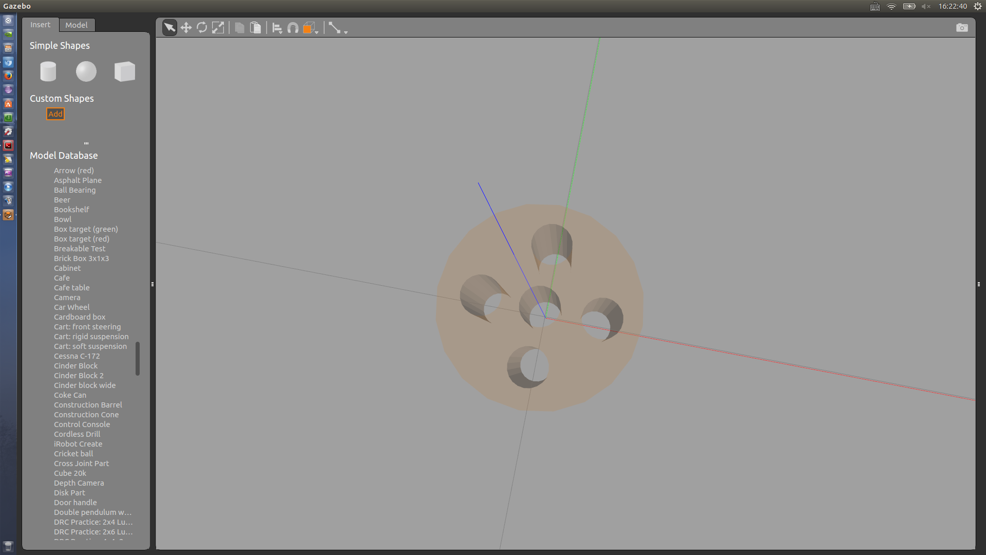
On the right, you can see the path extracted from your SVG. The red points arethe summit of the triangulation of the extruded 3D model.
Set the thickness of the wheel to 0.025 m, and press OK. Your new link shouldappear in the 3D view.
A new link is created, and it comes with a default collision shape that isa copy of the generated 3D mesh.

Next, select Exit Model Editor from the File menu. Gazebo will prompt youto save the new model to disk. Press the Save and Exit button on the Exitdialog, and the Save Model dialog will appear.

Set the name of the new model to "HollowWheel", and fill in the information underthe Advanced Options section. Press the Save button.
Your new Gazebo model is now ready to roll ;-)


 1413
1413

 被折叠的 条评论
为什么被折叠?
被折叠的 条评论
为什么被折叠?
 到【灌水乐园】发言


