


文章目录
前言
ArduPilot是一个多功能和开源的自动驾驶系统,支持多种车辆类型:多旋翼、传统直升机、固定翼飞机、船只、潜水器、无人车等。其源代码是由一大群专业人士和爱好者开发。
官方wiki:
https://ardupilot.org/ardupilot/
https://ardupilot.org/dev/
本教程主要是讲解基于ArduPilot固件的二次开发,适用于没有任何相关开发经验的朋友。
学习交流可加文章底部微信名片
硬件:
超维USV-M系列无人船
pix2.4.8飞控
软件:
ArduPilot 4.4
QGC4.2
安装好编译环境的虚拟机:
https://cwkj-tech.yuque.com/bsge84/uav-m1/cuut9sq5sci8c5wr
ArduPilot二次开发零基础教程(一):概述
课程内容暂时包括下面这些,后面有空了会继续补充
一、概述
二、开发环境搭建
三、多旋翼MAVROS自主控制接口
四、无人船(车)MAVROS自主控制接口
编译
cd hyper-drone/
source compile.sh
然后启动仿真,在ardupilot/Rover目录下执行:
../Tools/autotest/sim_vehicle.py -f rover

打开仿真后,新建apm.launch如下:
<launch>
	<!-- vim: set ft=xml noet : -->
	<!-- example launch script for ArduPilot based FCU's -->

	<arg name="fcu_url" default="udp://127.0.0.1:14551@14555" />
	<arg name="gcs_url" default="" />
	<arg name="tgt_system" default="1" />
	<arg name="tgt_component" default="1" />
	<arg name="log_output" default="screen" />
	<arg name="fcu_protocol" default="v2.0" />
	<arg name="respawn_mavros" default="false" />

	<include file="$(find mavros)/launch/node.launch">
		<arg name="pluginlists_yaml" value="$(find mavros)/launch/apm_pluginlists.yaml" />
		<arg name="config_yaml" value="$(find mavros)/launch/apm_config.yaml" />

		<arg name="fcu_url" value="$(arg fcu_url)" />
		<arg name="gcs_url" value="$(arg gcs_url)" />
		<arg name="tgt_system" value="$(arg tgt_system)" />
		<arg name="tgt_component" value="$(arg tgt_component)" />
		<arg name="log_output" value="$(arg log_output)" />
		<arg name="fcu_protocol" value="$(arg fcu_protocol)" />
		<arg name="respawn_mavros" value="$(arg respawn_mavros)" />
	</include>
</launch>
然后启动apm.launch
roslaunch apm.launch
启动成功后如下:

然后启动guided控制节点:
在~/hyper-drone工作空间路径下打开终端执行:
source devel/setup.bash
rosrun apm_commd apm_commd_Rover
执行成功后打印如下:

仿真中的无人船(车)会自动切换到Guided模式,然后按指令自主的运动

五、二次开发基础
六、控制LED灯
七、自定义串口驱动
使用串口驱动的接口需要包含hal头文件
#include <AP_HAL/AP_HAL.h>
修改Rover.h
声明一个串口测试任务
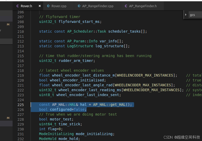
void uart_test();
获取AP_HAL命名空间中的HAL类的实例,并以常量引用的方式将其赋值给hal变量,这样hal就可以用来访问HAL实例的成员,但不能修改HAL实例本身。
const AP_HAL::HAL& hal = AP_HAL::get_HAL();
bool configured=false;
修改Rover.cpp
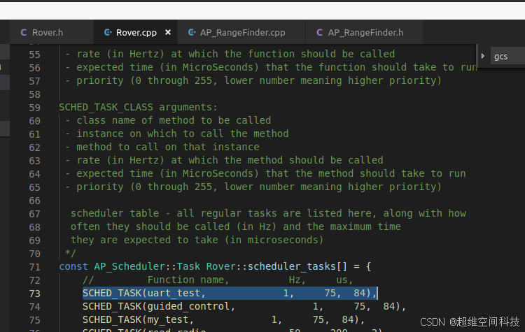
添加任务调度
SCHED_TASK(uart_test, 10, 75, 84),
实现串口收发
void Rover::uart_test()
{
    if(!configured)
    {
    hal.serial(1)->begin(57600);
    configured=true;
    }
     int16_t nbytes = hal.serial(1)->available();
     while (nbytes-- > 0) {
        char c = hal.serial(1)->read();
        gcs().send_text(MAV_SEVERITY_INFO,"byte=%c",c);
        hal.serial(1)->write(c);
     }
}
将pix2.4.8飞控的telem1口通过usb转ttl模块接到电脑的串口助手,通过串口助手向飞控发送数据,飞控接收到数据后,会原封不动的将数据再发回到串口助手。
7.1、使用Modbus协议控制伺服电机
使用的电机是AIM伺服电机,资料如下:
通过百度网盘分享的文件:2566984113YZ-AIM_2_63资料(1).rar
链接:https://pan.baidu.com/s/1H0Vmw80IE19eCr_jpCjAcQ?pwd=t05c
提取码:t05c
–来自百度网盘超级会员V7的分享
主要是在串口驱动的基础上,根据电机的协议,发送相应的Modbus指令,就可以控制电机转动。
我这里使用的绝对位置控制,代码如下:
/*  unsigned char *puchMsg ; 要进行 CRC 校验的消息  unsigned short usDataLen ; 消息中字节数 */
unsigned short Rover::CRC16(unsigned char *puchMsg, unsigned short usDataLen)
{
    /* CRC 高位字节值表 */
static unsigned char auchCRCHi[] = {
0x00, 0xC1, 0x81, 0x40, 0x01, 0xC0, 0x80, 0x41, 0x01, 0xC0, 0x80, 0x41, 0x00, 0xC1, 0x81, 0x40, 0x01, 0xC0, 0x80, 0x41, 0x00, 0xC1, 0x81, 0x40, 0x00, 0xC1, 0x81, 0x40, 0x01, 0xC0, 0x80, 0x41, 0x01, 0xC0, 0x80, 0x41, 0x00, 0xC1, 0x81, 0x40, 0x00, 0xC1, 0x81, 0x40, 0x01, 0xC0, 0x80, 0x41, 0x00, 0xC1, 0x81, 0x40, 0x01, 0xC0, 0x80, 0x41, 0x01, 0xC0, 0x80, 0x41, 0x00, 0xC1, 0x81, 0x40, 0x01, 0xC0, 0x80, 0x41, 0x00, 0xC1, 0x81, 0x40, 0x00, 0xC1, 0x81, 0x40, 0x01, 0xC0, 0x80, 0x41, 0x00, 0xC1, 0x81, 0x40, 0x01, 0xC0, 0x80, 0x41, 0x01, 0xC0, 0x80, 0x41, 0x00, 0xC1, 0x81, 0x40, 0x00, 0xC1, 0x81, 0x40, 0x01, 0xC0, 0x80, 0x41, 0x01, 0xC0, 0x80, 0x41, 0x00, 0xC1, 0x81, 0x40, 0x01, 0xC0, 0x80, 0x41, 0x00, 0xC1, 0x81, 0x40, 0x00, 0xC1, 0x81, 0x40, 0x01, 0xC0, 0x80, 0x41, 0x01, 0xC0, 0x80, 0x41, 0x00, 0xC1, 0x81, 0x40, 0x00, 0xC1, 0x81, 0x40, 0x01, 0xC0, 0x80, 0x41, 0x00, 0xC1, 0x81, 0x40, 0x01, 0xC0, 0x80, 0x41, 0x01, 0xC0, 0x80, 0x41, 0x00, 0xC1, 0x81, 0x40, 0x00, 0xC1, 0x81, 0x40, 0x01, 0xC0, 0x80, 0x41, 0x01, 0xC0, 0x80, 0x41, 0x00, 0xC1, 0x81, 0x40, 0x01, 0xC0, 0x80, 0x41, 0x00, 0xC1, 0x81, 0x40, 0x00, 0xC1, 0x81, 0x40, 0x01, 0xC0, 0x80, 0x41, 0x00, 0xC1, 0x81, 0x40, 0x01, 0xC0, 0x80, 0x41, 0x01, 0xC0, 0x80, 0x41, 0x00, 0xC1, 0x81, 0x40, 0x01, 0xC0, 0x80, 0x41, 0x00, 0xC1, 0x81, 0x40, 0x00, 0xC1, 0x81, 0x40, 0x01, 0xC0, 0x80, 0x41, 0x01, 0xC0, 0x80, 0x41, 0x00, 0xC1, 0x81, 0x40, 0x00, 0xC1, 0x81, 0x40, 0x01, 0xC0, 0x80, 0x41, 0x00, 0xC1, 0x81, 0x40, 0x01, 0xC0, 0x80, 0x41, 0x01, 0xC0, 0x80, 0x41, 0x00, 0xC1, 0x81, 0x40
};
/* CRC 低位字节值表*/
static unsigned char auchCRCLo[] = {
0x00, 0xC0, 0xC1, 0x01, 0xC3, 0x03, 0x02, 0xC2, 0xC6, 0x06, 0x07, 0xC7, 0x05, 0xC5, 0xC4, 0x04, 0xCC, 0x0C, 0x0D, 0xCD, 0x0F, 0xCF, 0xCE, 0x0E, 0x0A, 0xCA, 0xCB, 0x0B, 0xC9, 0x09, 0x08, 0xC8, 0xD8, 0x18, 0x19, 0xD9, 0x1B, 0xDB, 0xDA, 0x1A, 0x1E, 0xDE, 0xDF, 0x1F, 0xDD, 0x1D, 0x1C, 0xDC, 0x14, 0xD4, 0xD5, 0x15, 0xD7, 0x17, 0x16, 0xD6, 0xD2, 0x12, 0x13, 0xD3, 0x11, 0xD1, 0xD0, 0x10, 0xF0, 0x30, 0x31, 0xF1, 0x33, 0xF3, 0xF2, 0x32, 0x36, 0xF6, 0xF7, 0x37, 0xF5, 0x35, 0x34, 0xF4, 0x3C, 0xFC, 0xFD, 0x3D, 0xFF, 0x3F, 0x3E, 0xFE, 0xFA, 0x3A, 0x3B, 0xFB, 0x39, 0xF9, 0xF8, 0x38, 0x28, 0xE8, 0xE9, 0x29, 0xEB, 0x2B, 0x2A, 0xEA, 0xEE, 0x2E, 0x2F, 0xEF, 0x2D, 0xED, 0xEC, 0x2C, 0xE4, 0x24, 0x25, 0xE5, 0x27, 0xE7, 0xE6, 0x26, 0x22, 0xE2, 0xE3, 0x23, 0xE1, 0x21, 0x20, 0xE0, 0xA0, 0x60, 0x61, 0xA1, 0x63, 0xA3, 0xA2, 0x62, 0x66, 0xA6, 0xA7, 0x67, 0xA5, 0x65, 0x64, 0xA4, 0x6C, 0xAC, 0xAD, 0x6D, 0xAF, 0x6F, 0x6E, 0xAE, 0xAA, 0x6A, 0x6B, 0xAB, 0x69, 0xA9, 0xA8, 0x68, 0x78, 0xB8, 0xB9, 0x79, 0xBB, 0x7B, 0x7A, 0xBA, 0xBE, 0x7E, 0x7F, 0xBF, 0x7D, 0xBD, 0xBC, 0x7C, 0xB4, 0x74, 0x75, 0xB5, 0x77, 0xB7, 0xB6, 0x76, 0x72, 0xB2, 0xB3, 0x73, 0xB1, 0x71, 0x70, 0xB0, 0x50, 0x90, 0x91, 0x51, 0x93, 0x53, 0x52, 0x92, 0x96, 0x56, 0x57, 0x97, 0x55, 0x95, 0x94, 0x54, 0x9C, 0x5C, 0x5D, 0x9D, 0x5F, 0x9F, 0x9E, 0x5E, 0x5A, 0x9A, 0x9B, 0x5B, 0x99, 0x59, 0x58, 0x98, 0x88, 0x48, 0x49, 0x89, 0x4B, 0x8B, 0x8A, 0x4A, 0x4E, 0x8E, 0x8F, 0x4F, 0x8D, 0x4D, 0x4C, 0x8C, 0x44, 0x84, 0x85, 0x45, 0x87, 0x47, 0x46, 0x86, 0x82, 0x42, 0x43, 0x83, 0x41, 0x81, 0x80, 0x40
};
unsigned char uchCRCHi = 0xFF ; /* 高 CRC 字节初始化 */
unsigned char uchCRCLo = 0xFF ; /* 低 CRC 字节初始化 */
unsigned uIndex ; /* CRC 循环中的索引 */
while (usDataLen--) /* 传输消息缓冲区 */
{
uIndex = uchCRCHi ^ *puchMsg++ ; /* 计算 CRC */
uchCRCHi = uchCRCLo ^ auchCRCHi[uIndex];
uchCRCLo = auchCRCLo[uIndex] ;
}
return (uchCRCHi << 8 | uchCRCLo);
}

void Rover::uart_test()
{
//    gcs().send_text(MAV_SEVERITY_INFO,"test");
    if(!configured)
    {
    hal.serial(1)->begin(115200);
    configured=true;
    }
    if(!enmodbus)
    {
        uint8_t req_buf[]={0x00,0x06,0x00,0x00,0x00,0x01,0x49,0xDB,0xCC};
        const uint8_t req_buf_len = sizeof(req_buf);
        hal.serial(1)->write(req_buf, req_buf_len);
    }
     int16_t nbytes = hal.serial(1)->available();
     while (nbytes-- > 0) {
        char c = hal.serial(1)->read();
        gcs().send_text(MAV_SEVERITY_INFO,"byte=%c",c);

        hal.serial(1)->write(c);
     }
     servo_pos=servo_pos+2000;
    uint8_t pu24_32=servo_pos>>24&0xff;
    uint8_t pu16_23=servo_pos>>16&0xff;
    uint8_t pu8_15=servo_pos>>8&0xff;
    uint8_t pu0_7=servo_pos&0xff;

         uint8_t req_buf[] = {
            0x00,                       // address
            0x7b, // function code
            pu24_32, // PU:24~31
            pu16_23, // PU:16~23
            pu8_15,  // PU:8~15
            pu0_7,  // PU:0~7
            0,    // crc high
            0     // crc low
    }
    ;
    const uint8_t req_buf_len = sizeof(req_buf);

    // fill in crc bytes
    uint16_t crc = CRC16(req_buf, req_buf_len-2);
    req_buf[req_buf_len - 1] = LOWBYTE(crc);
    req_buf[req_buf_len - 2] = HIGHBYTE(crc);

    // send request to device
    hal.serial(1)->write(req_buf, req_buf_len);
}
将电机的485口通过485转ttl模块接到飞控的telem1口就可以控制电机不停的转动。
八、Guided控制接口
完整代码仓库:https://gitee.com/Mbot_admin/ardu-pilot-cwkj.git
添加自定义任务:
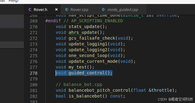
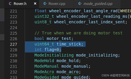
修改Rover.h
添加:
void guided_control();
添加时间戳和标志位
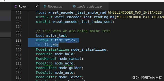
uint64_t time_stick;
int flag=0;
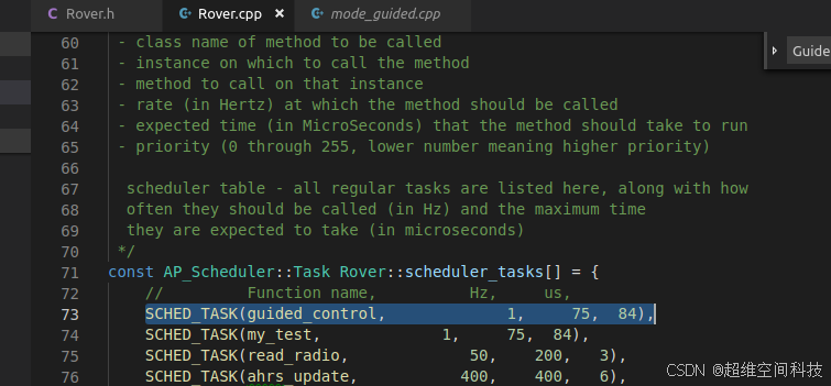
修改Rover.cpp
添加任务:
SCHED_TASK(guided_control, 1, 75, 84),
添加guided控制代码:
void Rover::guided_control()
{

    AP::arming().arm(AP_Arming::Method::AUXSWITCH, true);
    if(rover.control_mode->mode_number()!=15||!AP_Notify::flags.armed)
    {
        rover.set_mode(mode_guided, ModeReason::RC_COMMAND);
         AP::arming().arm(AP_Arming::Method::AUXSWITCH, true);
         time_stick=AP_HAL::micros64();
    }
    else
    {
    if(flag==0&&AP_HAL::micros64()-time_stick<10000000)
    {
             Location target_loc;
        target_loc.lat=111;
        target_loc.lng=11;
        if(rover.mode_guided.set_desired_location(target_loc))
        {
          gcs().send_text(MAV_SEVERITY_INFO,"control global position");
        }
        if(AP_HAL::micros64()-time_stick>8000000)
            {
             flag++;
             time_stick=AP_HAL::micros64();
            }

    }
         if(flag==1&&AP_HAL::micros64()-time_stick<10000000)
          {
             rover.mode_guided.set_desired_heading_and_speed(18000,5);
            if(AP_HAL::micros64()-time_stick>8000000)
            {
             flag++;
             time_stick=AP_HAL::micros64();
            }
             gcs().send_text(MAV_SEVERITY_INFO,"heading_and_speed");
    }
         if(flag==2&&AP_HAL::micros64()-time_stick<10000000)
          {
             rover.mode_guided.set_desired_turn_rate_and_speed(18000,5);
            if(AP_HAL::micros64()-time_stick>8000000)
            {
             flag++;
             time_stick=AP_HAL::micros64();
            }
             gcs().send_text(MAV_SEVERITY_INFO,"turn_rate_and_speed");
    }
    if(flag==3&&AP_HAL::micros64()-time_stick<10000000)
    {
             rover.mode_guided.set_steering_and_throttle(1,1);
            if(AP_HAL::micros64()-time_stick>8000000)
            {
             flag++;
             time_stick=AP_HAL::micros64();
            }
                gcs().send_text(MAV_SEVERITY_INFO,"steering_and_throttle");
    }
    }
}
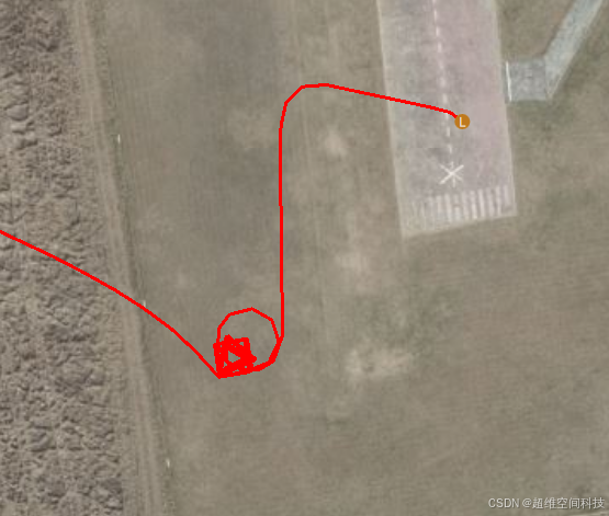
启动仿真,在Rover文件夹下启动
../Tools/autotest/sim_vehicle.py -f rover -I0 --sysid=1
然后打开地面站,过一段时间无人船定位初始化完后,会自动的切换到guided模式根据程序设定运动
九、输出自定义PWM信号
十、添加自定义MAVLINK消息和QGC通信
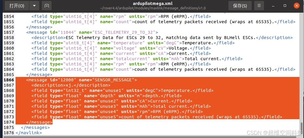
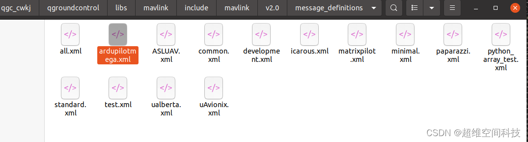
1、添加消息定义
在下面的文件添加自定义消息的xml定义
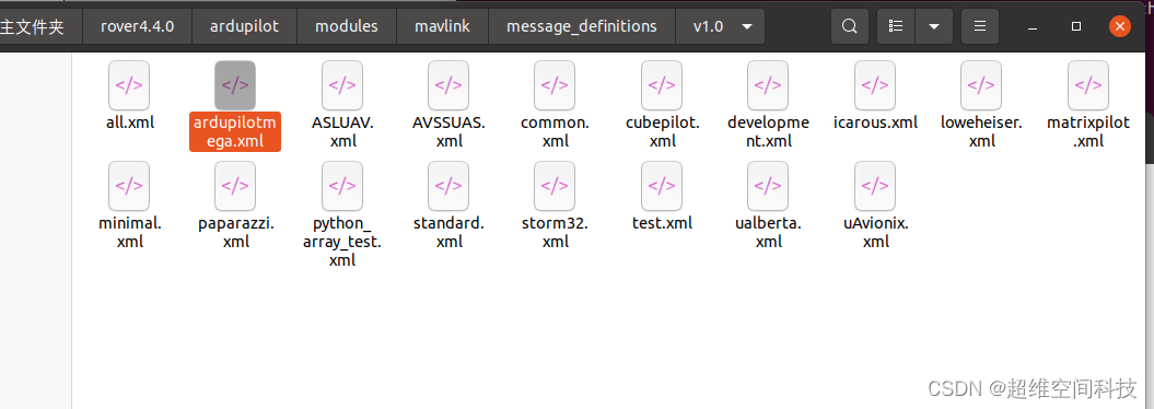
我这里添加如下:
   <message id="12000" name="SENSOR_MESSAGE">
      <description>xj.</description>
      <field type="int32_t" name="unuse1" units="degC">Temperature.</field>
      <field type="float" name="depth" units="m">depth.</field>
      <field type="float" name="unuse2" units="cA">Current.</field>
      <field type="float" name="unuse3" units="mAh">Total current.</field>
      <field type="float" name="unuse4" units="rpm">RPM (eRPM).</field>
      <field type="float" name="unuse5">count of telemetry packets received (wraps at 65535).</field>
    </message>
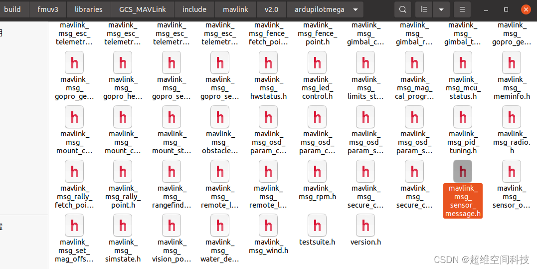
然后编译固件,会生成相应的消息头文件
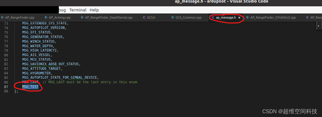
2、添加消息发送
修改ap_message.h
添加MSG_TEST,上面的逗号不要忘记
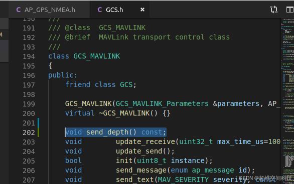
修改libraries/GCS_MAVLink/GCS.h
添加
void send_depth() const;
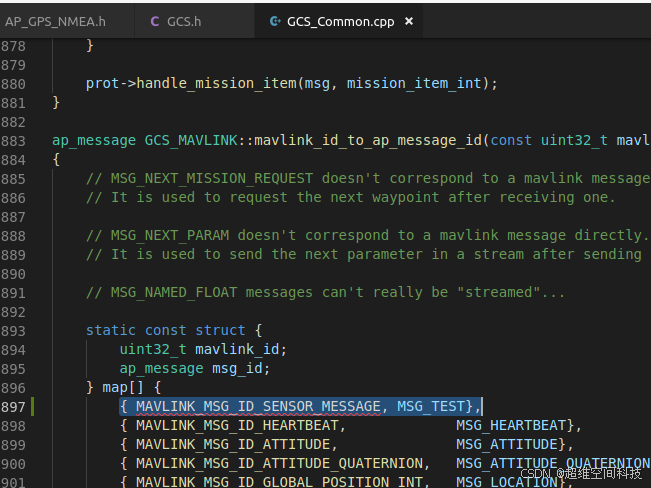
修改libraries/GCS_MAVLink/GCS_Common.cpp
添加:
{ MAVLINK_MSG_ID_SENSOR_MESSAGE, MSG_TEST},
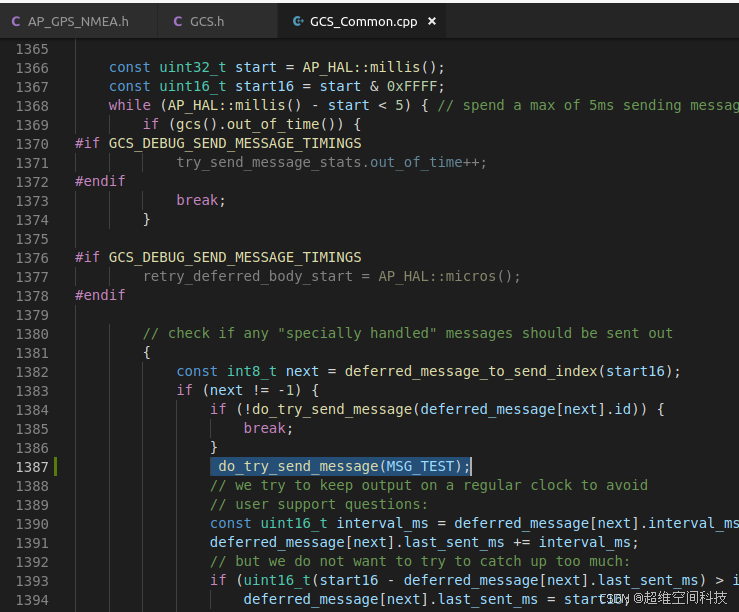
添加:
do_try_send_message(MSG_TEST);
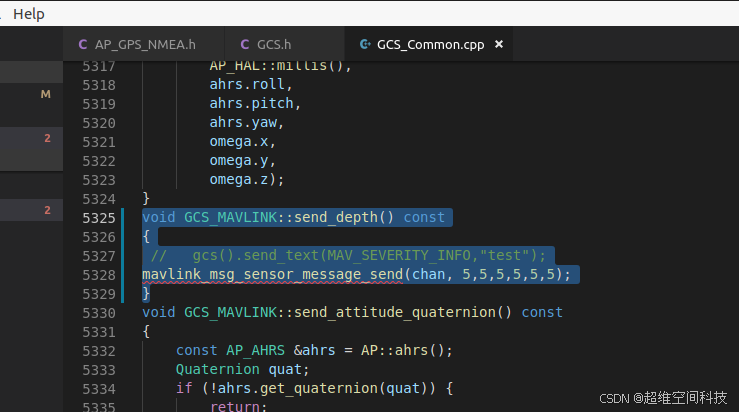
添加:
void GCS_MAVLINK::send_depth() const
{
 //   gcs().send_text(MAV_SEVERITY_INFO,"test");
mavlink_msg_sensor_message_send(chan, 5,5,5,5,5,5);
}
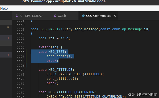
添加:
case MSG_TEST:
    send_depth();
    break;
3、QGC接收消息
修改下面的xml文件,加上apm里同样的消息,然后用mavgen生成消息库替换掉原来的库,再重新编译QGC即可。
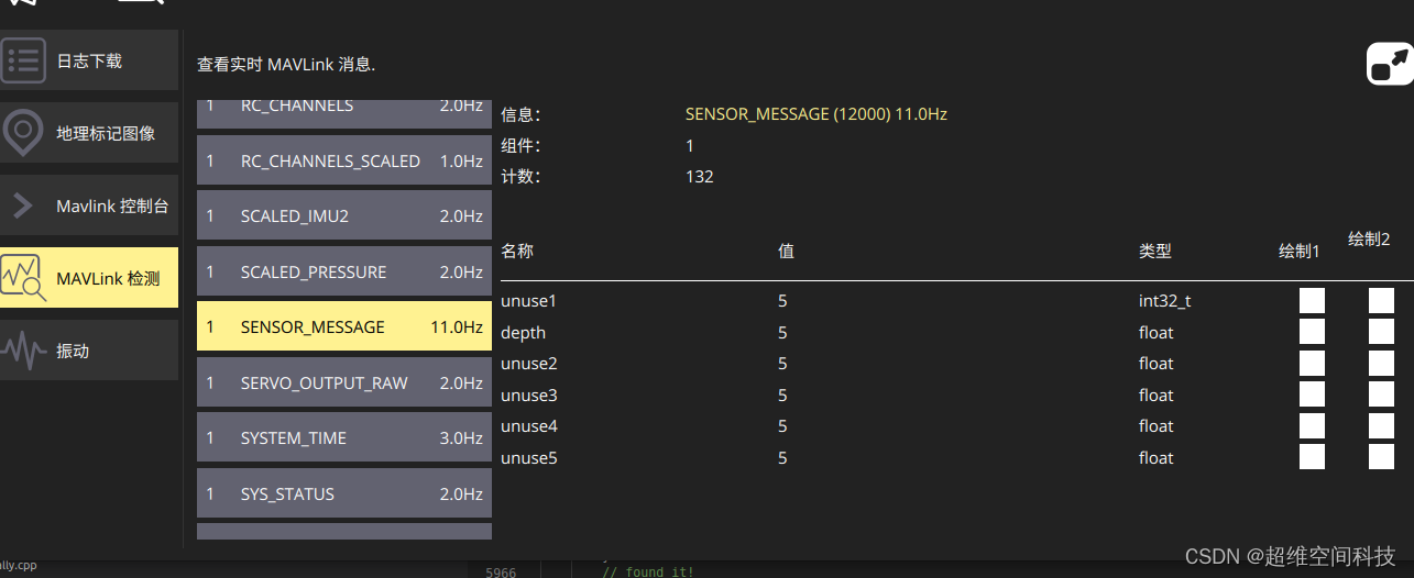
4、测试
下载好固件,重新编译地面站。可以看到地面站能显示接收到的自定义数据。
十一、自定义日志
十二、自定义参数
本教程是根据apm官网wiki操作的,也可以直接参考官方教程
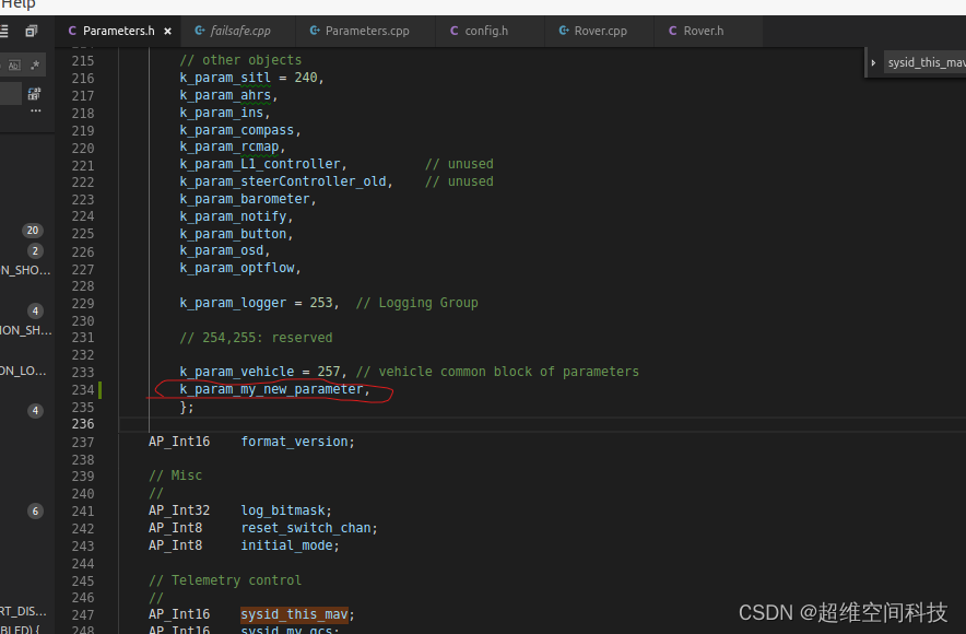
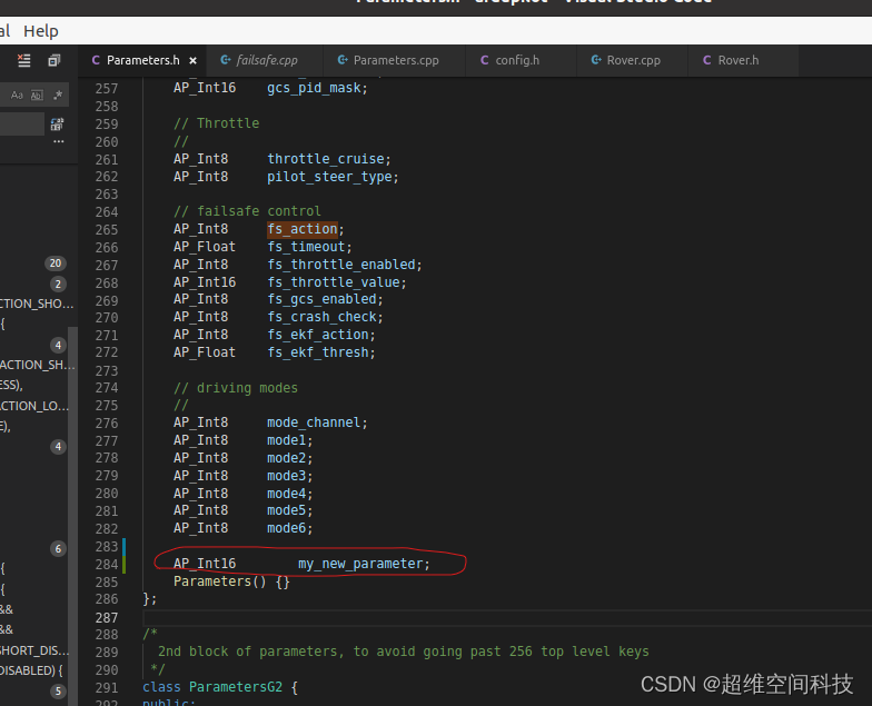
1、修改Parameters.h
修改Parameters.h,添加如下:
k_param_my_new_parameter,
AP_Int16 my_new_parameter;
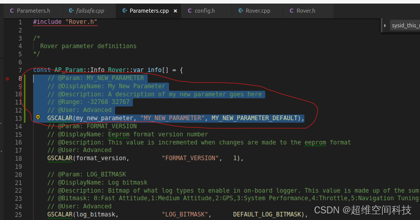
2、修改Parameters.cpp
// @Param: MY_NEW_PARAMETER
// @DisplayName: My New Parameter
// @Description: A description of my new parameter goes here
// @Range: -32768 32767
// @User: Advanced
GSCALAR(my_new_parameter, "MY_NEW_PARAMETER", MY_NEW_PARAMETER_DEFAULT),
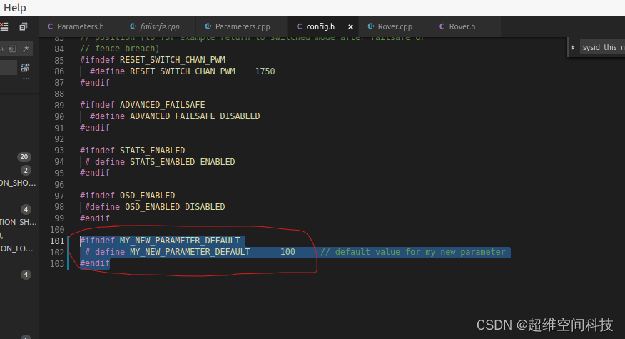
3、修改config.h
#ifndef MY_NEW_PARAMETER_DEFAULT
 # define MY_NEW_PARAMETER_DEFAULT      100     // default value for my new parameter
#endif
4、添加打印
经过前三步,参数已经添加到固件了,这一步就是调用参数并打印到地面站
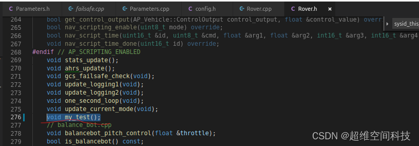
修改Rover.h
void my_test();
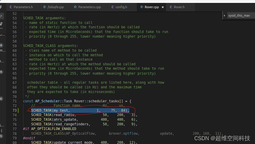
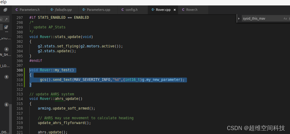
修改Rover.cpp
SCHED_TASK(my_test, 1, 75, 84),
void Rover::my_test()
{
     gcs().send_text(MAV_SEVERITY_INFO,"%d",(int16_t)g.my_new_parameter);
}
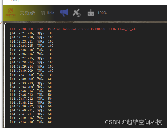
5、测试
编译烧录到飞控,然后连上地面站
可以在参数列表里搜索到参数

地面站会实时打印当前的参数值


 1337
1337

 被折叠的 条评论
为什么被折叠?
被折叠的 条评论
为什么被折叠?
 到【灌水乐园】发言


